Hardy Cross Method – Sizing a Ring Main (FREE Spreadsheet)
Flow rate and friction loss in a pipe network system can be difficult to calculate. When the pipe network is in a ring main (also known as a closed-loop) formation, the calculations are extra difficult. This difficult calculation is very common for fire hydrant ring main size designs and the ring main design calculations.
Download your free PDF of this article below.
Flow rate and friction loss in a pipe network system can be difficult to calculate. When the pipe network is in a ring main (also known as a closed-loop) formation, the calculations are extra difficult.
This difficult calculation is very common for fire hydrant ring main size designs and the ring main design calculations.
The Hardy Cross method helps significantly with this calculation provided you have the following information:
- Pipe Lengths; and
- Flow Rates.
How the Hardy Cross method works
Water always takes the path of least resistance. Whether that is filling a water bottle, entering cracks in a road, or going through a pipe network.
To determine how water is distributed in a ring main pipe network, an iterative calculation needs to be performed until the friction loss caused by the flow rate in a clockwise direction is equal to the friction loss caused by the flow rate in the anti-clockwise direction i.e. the path of resistance is equal
Free Hardy Cross Method spreadsheet (and how the spreadsheet works)
You can download a free spreadsheet here to use on your next project.
Following the steps below will assist in learning how the calculation and spreadsheet work:
1. Flow Rates
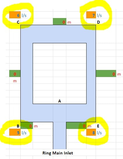
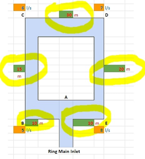
For every outlet there is on the ring main, enter the flow rate into the orange cells (enter ‘0’ into any cells that you do not need to use).
In this example, we have entered:
- 5 l/s at Point B;
- 6 l/s at Point C;
- 7 l/s at Point D; and
- 8 l/s at Point E.

2. Pipe Lengths
Add the pipe lengths between every outlet into the green cells.
In this example, we have entered:
- 10m between Point A and B;
- 15m between Point B and C;
- 30m between Point C and D;
- 20m between Point D and E; and
- 10m between Point A and E.
3. Estimate the Flow Rate Distribution
Estimate how much of the flow rate will go clockwise and anti-clockwise, and enter it into the table under column ‘Q’.
In this example, we estimated:
- 14.5 l/s will go clockwise (14.5 l/s from Point A to Point B, 9.5 l/s from Point B to Point C, and 3.5 l/s from Point C to Point D); and
- 11.5l/s will go anti-clockwise (11.5 l/s from Point A to Point E and 3 l/s from Point E to Point D).

4. 1st Calculation
With this information provided, the 1st version of the calculation can be undertaken.
The calculation has three parts to it:
Length * Flow Rate ^ 2 – this formula/calculation is applied to every section of the pipe. Where the flow rate is going in an anti-clockwise direction, the number is made negative.
2 * Length * Flow Rate – this formula/calculation is applied to every section of the pipe.
– Length * Flow Rate ^ 2 / 2 * Length * Flow Rate – if the result from this formula/calculation is negligible, the process can stop here. If the result is too high (this depends on how accurate you need to be) then the calculation needs to be iterated.

In this example, we will iterate the calculation until we get a smaller result.
5. Update Flow Rates
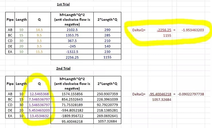
To start the second calculation, the original result (-1.953463203) is added to the clockwise flow rates and subtracted from the anti-clockwise flow rates.
You can see the updated flow rate results in column ‘Q’ below:
6. 2nd Calculation
The same calculation that was described in Step 4 is undertaken with the updated flow rates. This time the result is negligible so we stop the calculations.
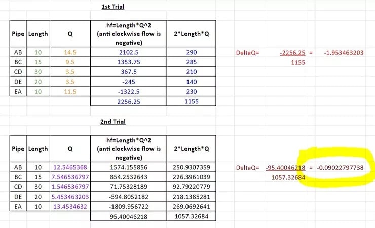
Again, it is up to you to decide what is negligible. If the result is still too high for you, using a Pressure Drop Calculator you can iterate the calculation again, following the same process described in Step 5.
7. Pipe Sizing & Friction Loss Calculations (Hardy Cross Method)
Now that you know how much flow rate you have going through each section of pipe (the Q column on the last iteration of the calculation), you can choose which pipe size you would like to use.
And once you have selected the pipe size, with both a pipe volume calculator and Mains water pipe size calculator you can follow normal friction loss calculation methods to determine how much pressure loss there will be through that Xmm pipe, of Xm length, at X l/s flow rate.
Things to be aware of when using the Hardy Cross method:
- The pipe sizes need to be the same throughout the ring main. If the pipe sizes vary, extra friction will be created and this will alter the direction of the flow rate (the path of least resistance changes)
- This methodology does not work well for domestic systems where flow rates are diversified. You can learn more about why that is here.
h2x: All-In-One Tool for Calculating, Designing, Estimating, and Paperwork

What's in the Pipeline?
Get technical resources delivered to your inbox weekly!
Testimonials
What Installers Say
What Consultants Say
A game changer for the humble plumber. Incredible.
Brad Winkel
Director at Queenstown Plumbing
Brilliant, simple and easy to use. Game changer.
James Major
Director at Hubb
Big time game changer to the industry!
Viv Jude
Director at UHC
Incredible software! Super user-friendly and allows you to save so much time.
Devni Gamage
Engineer at DMA
h2x is great software, our company use it nearly every day. It is easy to use with direct conversion from h2x to Revit.
Callum Craig
Engineer at WDE
h2x is fantastic software. It is very easy to use and the ability to output to Revit is a fantastic time saver.
Joe Kirrane
Engineer at MEP


