Sizing a Ring Main with a Diversified Flow Rate
It appears that sizing a ring main accurately is a black art within the industry that has no endorsed engineering process or calculations. When developing H2X, we explored various options as we assessed the most fit for purpose solution to include in our calculations. The different options and each of their pros and/or cons are

It appears that sizing a ring main accurately is a black art within the industry that has no endorsed engineering process or calculations.
When developing H2X, we explored various options as we assessed the most fit for purpose solution to include in our calculations. The different options and each of their pros and/or cons are summarised below.
*Note – when the flow rate is not diversified, the Hardy Cross method can be used, learn more about that here.
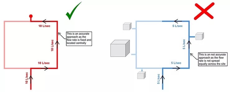
Option 1 – Split the flow rate 50/50
This concept makes sense from a high level, but when it comes down to the detail, it really lacks accuracy.
How do you determine the pressure loss at each point in this system? Does the flow rate diminish at all?
Exploring a bit further took us to option 2.
Option 2 – Find the centre of the ring main & multiply the pressure loss by 0.XX
This is probably the most common method of sizing pipes and determining the pressure loss in a ring main.
This is a common calculation method that is used for fixed flow rates such as in fire hydrant system designs; in those scenarios it works well. However, it is not accurate when the flow rate is diversified.
The reason it does not work when the flow rate is diversified is because… where is the flow rate going? It changes in every scenario.
By taking it to the furthest point in the ring main, you are treating the diversified flow rate like a fire hydrant.
In some instances, you can have a large demand on one side of the ring main; this could be a riser offset, cooling towers, or if the ring main was on a site there may be a huge building on the site with lots of smaller ones.
In most cases this is a conservative way to do it, but in all cases it is an inaccurate way to do it.
To get over this issue, we explored splitting the flow rates up based on % of their contribution to the diversified flow rate – this leads us to the next option we investigated.

Option 3 – Spread the flow rates based on % of contribution to the diversified flow rate
This option sounded sensible and appeared to be a logical approach to take.
Initially, it seemed to produce sensible and logical results too as we simulated the calculation method on a large site that consisted of many large buildings.
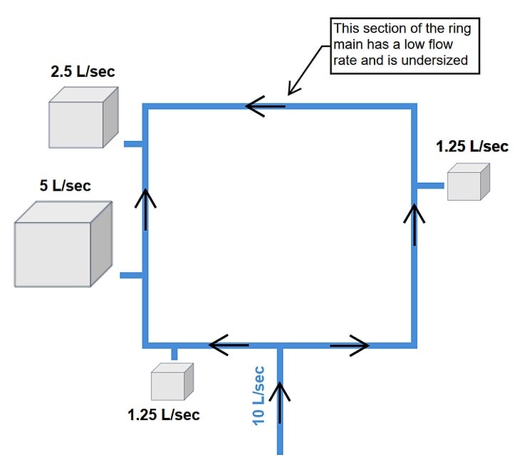
However, when following this procedure on a floor internal to a building, the results made it clear that this is not an accurate approach to be taking. It almost always results in the furthest part of the ring main being 15mm as it only has a trickle of flow through it.
This doesn’t work for obvious reasons, mainly because a ring main is usually there to provide redundancy in the event of a shutdown to part of the floor. When the shutdown happens, the 15mm pipe is not going to live up to its expectations.
This led us to option 4, the option that the software has adopted.

Option 4 – Size the ring main based on iteratively closing each isolation valve and sizing to the worst case result
This option works well because it is a solution that can be verified and has solid engineering principles and practices behind it.
The reason this is thought to not be common practice in the industry is because it takes a lot of iterative calculations which is difficult to do by hand. However, it provides a fit for purpose solution.
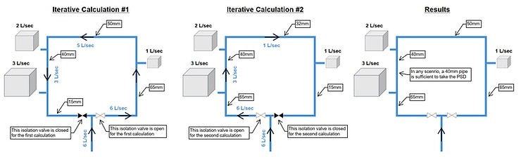
Generally, the findings are that the pipe size either side of the inlet to the ring main are sized to the peak demand of the ring main and towards the centre of the ring main the pipe size reduces by one or two sizes.
How do you currently deal with determining pressure loss in ring mains with a diversified flow rate? Sign up for a free trial with H2X to try out this method of ring main calculations.
Meet the author

h2x Team
h2x write about heat loss calculations, HVAC design workflows, and MEP software tools that help teams design faster and more accurately.
Article Last Updated: November 19, 2024