The Importance of Calculating Residual & Static Pressure
Water pressure is an essential aspect of every plumbing system. Here, we explain the importance of calculating residual and static pressure.
Download your free PDF of this article below.
What is residual pressure?
The minimum pressure that you can expect in the system.
This is caused by the water operating under peak conditions (the maximum flow rate).
What is static pressure?
The maximum pressure that you can expect in the system.
This is caused by the water being ‘static’ (no flow rate).
Why are they important?
The water system operates between a peak flow rate (such as at 8am when everyone is showering before work) and a static flow rate (such as in the middle of the night when no one is using water).
When the flow rate increases, the water pressure decreases.
When the flow rate decreases, the water pressure increases.
Consequently, components in the system are exposed to a wide range of pressures.
This is important because every component in a water system has a minimum inlet pressure and a maximum inlet pressure. If you fall outside of this pressure range, the component will not function correctly.
For example, the pressure range for various components is shown below:
To ensure that you fall within the minimum and maximum pressure range, you must calculate both the residual and static pressure in the system.
What impacts a building’s pressure?
The local water utility will inform you of how much pressure there is where you connect to their water main.
The pressure throughout your building is then affected by water travelling through:
- Pipes
- Valves
- Fittings
- Changes in Height
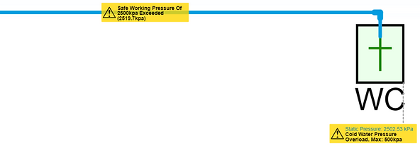
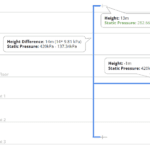
This can be visualised in the below image taken from h2x’s design software:
Calculating Residual and Static Pressure Example
In this example, we will calculate the residual and static pressure in a simple scenario of supplying one hose tap in a car park.
Project Information
Utility Information: Building Information:
Residual Pressure: 270 kPa Floor Height: 15m
Static Pressure: 620 kPa
Water Main Height: 14m
Fixture Information: System Information:
Height Above Floor: 0.5m Flow Rate: 0.5 L/s
Minimum Inlet Pressure: 200 kPa Pipe Diameter: 25mm
Maximum Inlet Pressure: 500 kPa
Residual Pressure Calculation
The peak flow rate causes pressure loss through:
- Pipes – calculated using the Darcy Weisbach equation (try out calculator)
- Valves – calculated using their kV/zeta values or manufacturer’s data
- Fittings – calculated using their kV/zeta values
There is also pressure loss caused by the vertical height difference between the water main and the hose tap – this is not affected by flow rate.
Utility Residual Pressure = 270 kPa
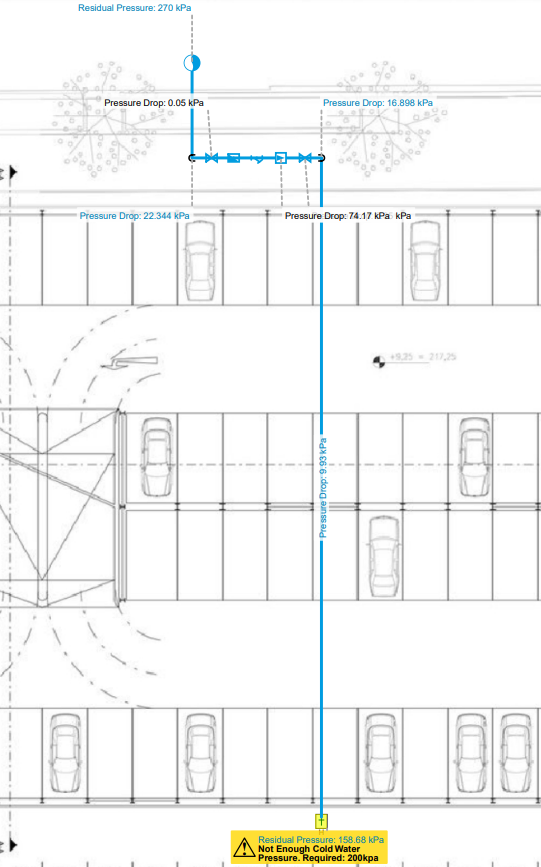
Pipe Pressure Loss = – 17.43 kPa (20.5m x 0.85 kPa/m)
Valve Pressure Loss = – 76.52 kPa (0.05 + 0.3 + 1.5 + 74.17 + 0.05 kPa)
Fitting Pressure Loss = – 3.12 kPa (6 x 0.52 kPa)
Vertical Height Change = – 14.72 kPa (1.5m x 9.81 kPa)
Fixture Residual Pressure = 158 kPa
This can be visualised in the below image taken from h2x’s design software:
Static Pressure Calculation
Because there is no flow rate in a static pressure calculation, there is no pressure loss through the pipes, valves, or fittings.
Therefore, the vertical height difference is the only thing to take into account.
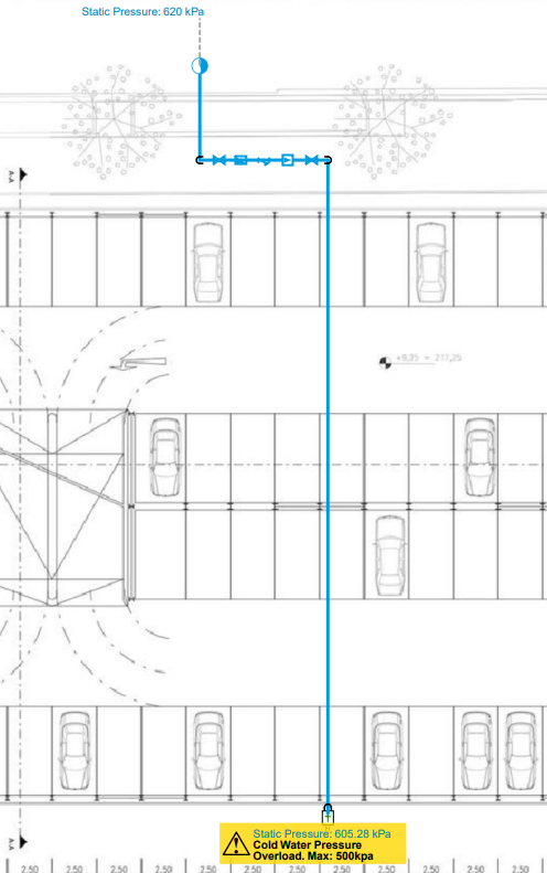
Utility Static Pressure = 620 kPa
Vertical Height Change = – 14.72 kPa (1.5m x 9.81 kPa)
Fixture Static Pressure = 605 kPa
This can be visualised in the below image taken from h2x’s design software:
What if there is not enough residual pressure?
If the residual pressure is below the minimum inlet pressure of a component in the system, you will generally need to add a booster pump.
For example, the residual pressure at the hose tap is 158 kPa (42 kPa below the minimum inlet pressure). If you add a booster pump to your design with additional pressure of 100 kPa, the pressure at the hose tap (258 kPa) will then fall within the 200 – 500 kPa pressure range.
What if there is too much static pressure?
If the static pressure exceeds the maximum inlet pressure of a component in the system, you will need to add a pressure reduction valve (PRV).
For example, the static pressure at the hose tap is 605 kPa (105 kPa over the maximum inlet pressure). If you add a PRV to your design and set the outlet pressure at 400 kPa, the pressure at the hose tap will then fall within the 200 – 500 kPa pressure range.
You can read more about designing PRVs in this blog post we wrote.
Can you have not enough residual pressure and too much static pressure?
Yes, this is relatively normal in high-rise buildings and/or areas where the utility has a wide pressure range in their network.
You will need both a PRV and a booster pump in your design so that your residual and static pressure both fall within the 200 – 500 kPa pressure range.
Conclusion
Failing to do your pressure calculations diligently could lead to designing a non-compliant system that will fail during operation.
We hope this blog has brought attention to the importance of calculating both the residual and static pressure on all of your projects.
h2x Engineering’s design software will automatically calculate the residual and static pressure based on your design layout.
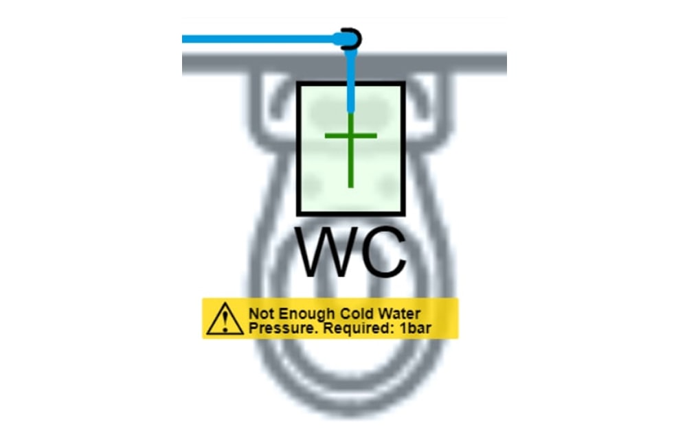
If you fall outside of the compliant range, warnings are provided to ensure the issue gets resolved before the design gets installed.
If you would like to try h2x on your next project, sign up for your free trial here.
FAQs
How does one accurately measure and calculate the residual static pressure in a duct system?
Accurately measuring and calculating residual static pressure in a duct system typically involves using specialised tools such as manometers or pressure gauges.
This process requires taking pressure readings at various points throughout the ductwork and comparing them to the design specifications to determine the residual static pressure.
Are there any industry standards or guidelines for acceptable levels of residual static pressure in ductwork?
While the article highlights the importance of calculating residual static pressure, it does not go into specific industry standards or guidelines for acceptable levels.
Readers may wonder if there are recommended ranges or thresholds that engineers should aim for when assessing residual static pressure in HVAC systems.
Can the calculation of residual static pressure vary based on different types of HVAC systems or configurations?
The article focuses on the significance of residual static pressure but does not explore whether the calculation method can vary depending on different HVAC system types or configurations.
Readers may be interested in understanding if factors such as duct size, layout, or equipment specifications impact how residual static pressure is calculated and interpreted in practice.
h2x: All-In-One Tool for Calculating, Designing, Estimating, and Paperwork

What's in the Pipeline?
Get technical resources delivered to your inbox weekly!
Testimonials
What Installers Say
What Consultants Say
A game changer for the humble plumber. Incredible.
Brad Winkel
Director at Queenstown Plumbing
Brilliant, simple and easy to use. Game changer.
James Major
Director at Hubb
Big time game changer to the industry!
Viv Jude
Director at UHC
Incredible software! Super user-friendly and allows you to save so much time.
Devni Gamage
Engineer at DMA
h2x is great software, our company use it nearly every day. It is easy to use with direct conversion from h2x to Revit.
Callum Craig
Engineer at WDE
h2x is fantastic software. It is very easy to use and the ability to output to Revit is a fantastic time saver.
Joe Kirrane
Engineer at MEP


