101 on Expansion Vessels (Includes Calculation Example)
Gain a comprehensive understanding of expansion vessels inside this informative blog. Includes a calculation example for practical insights.
In the realm of heating and cooling systems, the importance of understanding expansion vessels can’t be overstated.
These vital components, also known as expansion tanks, are pivotal in maintaining system safety and operational efficiency.
They counterbalance changes in fluid volume, and consequently pressure fluctuations, which occur due to variations in temperature.
What is an Expansion Vessel?
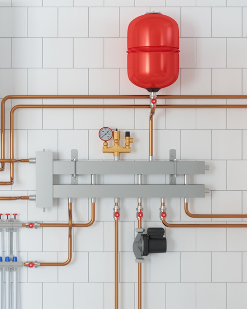
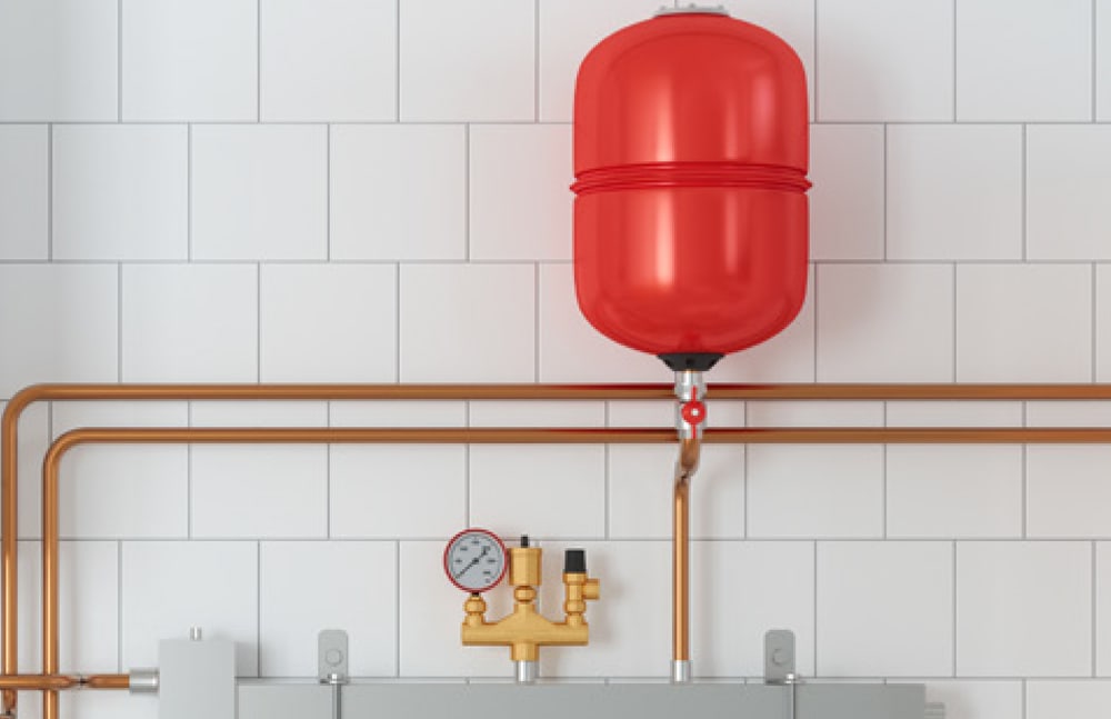
An expansion vessel, or expansion tank, is a device in a heating or cooling system that accommodates the extra volume of water produced when the system water is heated or cooled.
As the water heats up, it expands, and without a place to go, this increase in volume can cause a dramatic rise in pressure.
The expansion vessel provides the necessary ‘give’ in the system to handle this extra volume, preventing potential over-pressurisation damage.
Location of Expansion Vessels
Expansion vessels are required in systems where a closed circuit is subjected to a fluctuation in temperature e.g. heating and cooling systems.
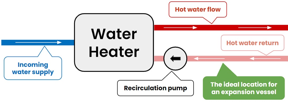
Ideally, they should be placed in a cooler section of the system, for instance, the return pipe close to the boiler or chiller.
This location ensures the expansion vessel can compensate for the vacuum formed when the water cools and contracts.
Moreover, to avoid the issue of pump cavitation, installing the vessel on the suction side of the recirculation pump is recommended.
Without a correctly sized expansion vessel, the system is exposed to potential risks.
The Consequences of Incorrect Calculating or Positioning
Improper calculation or positioning of an expansion vessel can lead to a range of problems:
– Undersized: this may result in excessive system pressure, potentially leading to system component failure.
– Oversized vessel: this can cause inefficiencies and unnecessary costs.
– Incorrect positioning: this can disrupt the vessel’s primary function of accommodating fluid volume changes, potentially leading to dangerous pressure build-ups or operational inefficiencies.
Factors that Influence the Sizing
System Volume
This is the volume of water in the system’s components e.g. the pipes, tanks, and emitters.
The volume will differ on every project due to the various system layouts and associated range of sizes.
Initial System Pressure
The initial system pressure is the incoming water pressure.
This data can usually be found within the system’s design specifications. In cases where it’s not readily available, a pressure gauge might be needed to measure this pressure.
1 bar (100 kPa / 14.5 psi) is commonly used for this
Maximum Allowable Pressure
The maximum allowable pressure is the peak pressure that a system can safely tolerate without causing damage to its components or risking a system failure.
This value is usually defined by the weakest component of the system e.g. the boiler or heat exchanger.
3 bar (300 kPa / 43.5 psi) is commonly used for this (recommended by CIBSE) but the manufacturer’s documentation is typically the best source for this information.
Initial System Temperature
The initial system temperature is the temperature of the incoming water before it is heated.
This number will vary based on your geographical location and the associated climate but will likely be around 5°C (41°F) in the winter months.
Maximum System Temperature
The maximum system temperature is the maximum operating temperature of the system.
90°C (194°F) is commonly used but the manufacturer’s documentation is typically the best source for this information.
Expansion Vessels Sizing: A Walkthrough
Having understood the crucial parameters, we now venture into the specifics of calculating the size of an expansion vessel.
Step 1 – Calculating the volume of the expanded fluid:
This is achieved using the formula:
X = V * (1 + (T_max – T_initial) * C)
Where:
X: the volume of the expanded fluid (L).
V: the system volume (L).
C: the volumetric expansion coefficient of the fluid (0.000214).
T_max: the maximum temperature (°C).
T_initial: initial temperature (°C).
Step 2 – Determining the volume of the expansion vessel:
Following the calculation of the expanded fluid volume, the expansion vessel’s volume can be computed using:
Vessel = X / ( 1 + (P_initial / (P_max – P_initial))
Where:
Vessel: the required expansion vessel volume (L).
P_max: the maximum allowable system pressure (bar).
P_initial: the initial system pressure (bar).
A Hypothetical Calculation: A Practical Demonstration
Consider a system with a water volume of 500L, an initial temperature (T_initial) of 10°C, and a maximum operating temperature (T_max) of 80°C.
The initial system pressure (P_initial) is set at 1.2 bar, with a maximum allowable system pressure (P_max) of 3 bar.
Step 1 – Calculate the volume of expanded water:
Inserting these values into the formula, we have:
X = 500L * (1 + (80 – 10) * 0.000214)
X = 500L * (1 + 70 * 0.000214)
X = 500L * 1.01284
X = 507.42L
Step 2 – Determine the volume of the expansion vessel:
Now, we can use this expanded water volume to calculate the required volume of the expansion vessel:
Vessel ≈ 507.42 L / (1 + (1.2 bar / (3 bar – 1.2 bar)))
Vessel ≈ 507.42 L / (1 + (1.2 bar / 1.8 bar))
Vessel ≈ 507.42 L / (1 + 0.6667)
Vessel ≈ 507.42 L / 1.6667
Vessel ≈ 304.14 L
Thus, for this hypothetical situation, an expansion vessel of approximately 305L would be required.
Conclusion
The critical process of accurately calculating and correctly positioning an expansion vessel is crucial in designing and operating heating and cooling systems.
Without this, the system may be subject to risks ranging from inefficiencies to component damage and failure.

The transformation of industries by the digital revolution is a story told many times over, and heating system design is no exception.
With the right software, like h2x Engineering’s Heating Design Software, you can drive efficiency and accuracy in your heating system projects.
Embracing the digital revolution in the form of heating design software, like that offered by h2x Engineering, is crucial for professionals who wish to stay competitive in the industry.
It offers a blend of convenience, precision, and efficiency that traditional methods cannot match.
Give your heating system designs the h2x advantage and experience the difference by booking a demo or by starting your free trial today!
h2x: All-In-One Tool for Calculating, Designing, Estimating, and Paperwork

What's in the Pipeline?
Get technical resources delivered to your inbox weekly!
Testimonials
What Installers Say
What Consultants Say
A game changer for the humble plumber. Incredible.
Brad Winkel
Director at Queenstown Plumbing
Brilliant, simple and easy to use. Game changer.
James Major
Director at Hubb
Big time game changer to the industry!
Viv Jude
Director at UHC
Incredible software! Super user-friendly and allows you to save so much time.
Devni Gamage
Engineer at DMA
h2x is great software, our company use it nearly every day. It is easy to use with direct conversion from h2x to Revit.
Callum Craig
Engineer at WDE
h2x is fantastic software. It is very easy to use and the ability to output to Revit is a fantastic time saver.
Joe Kirrane
Engineer at MEP
