Hot Water Recirculation Design in h2x
See how to set up, draw and calculate a hot water recirculation system in h2x, from design parameters and pipework to balancing and final results.
Designing a hot water recirculation system involves more than drawing a supply pipe and adding a return. Pipe sizes, heat loss, circulation flow, pressure loss and balancing all interact, so a change in one part of the system can affect calculations elsewhere.
h2x brings those calculations into the same workflow as the system layout. Instead of updating separate drawings and spreadsheets as the design changes, engineers can draw the system and review the calculated results as they work.
This guide shows the main steps involved in designing a hot water recirculation system in h2x. If you are looking for a broader explanation of how these systems work, including system types, controls and pump sizing, see our guide to hot water recirculating pumps.
Watch the Hot Water Design Workflow in h2x
The video below shows the complete workflow in h2x, from setting the initial design parameters through to reviewing the final circulation calculations.
The process covers:
- Setting the calculation parameters
- Adding the hot water source
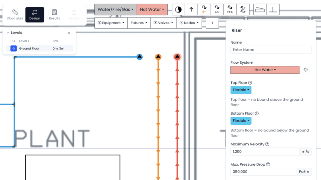
- Drawing the supply and return pipework
- Setting pipe heights
- Connecting fixtures and valves
- Reviewing circulation flow and pressure loss
- Checking pipe sizes and velocities
- Reviewing balancing valve requirements
1. Set the Hot Water Design Parameters
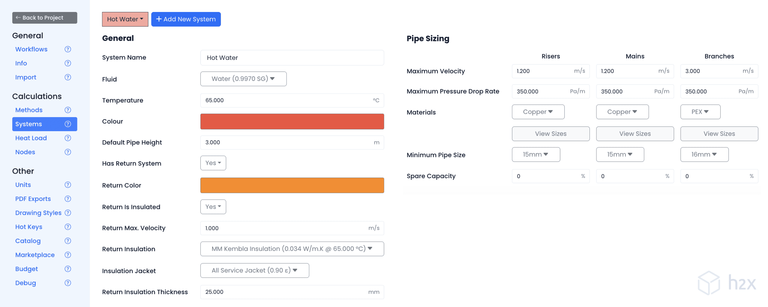
Before drawing the system, set the calculation parameters that h2x will use throughout the project.
These can include:
- Pipe material
- Insulation type and thickness
- Design velocity limits
- Flow to return temperature difference (ΔT)
- Other project-specific calculation settings
These inputs matter because they influence the results later in the design.
For example, pipe insulation affects distribution heat loss, while the selected flow to return ΔT influences the circulation flow required to maintain the intended return water temperature.
The correct values should come from the project requirements, applicable standards and equipment information rather than applying one set of assumptions to every design.
For more detail on the principles behind distribution heat loss, see our guide to calculating heat loss.
2. Add the Hot Water Source
Once the project settings are in place, add the hot water source to the system layout.
The exact plant arrangement will vary between projects, but defining the source gives the pipework a starting point and allows the supply and return system to connect back to the plant.
At this stage, the aim is to establish the overall system arrangement before moving into the detailed pipework.
3. Draw the Hot Water Supply and Return Pipework
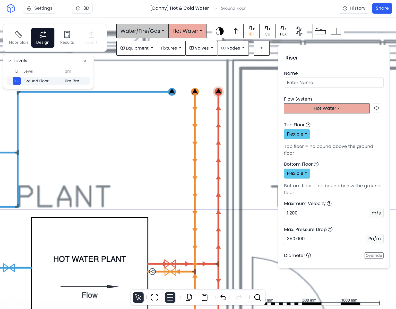
Next, draw the hot water distribution pipework from the source to the areas served by the system.
Where recirculation is required, add the return pipework so water can circulate back towards the hot water source.
Pipe heights can also be defined as the system is drawn. This helps the layout represent the actual route through the building rather than treating every pipe as though it sits on the same level.
As the network develops, h2x can use the connected system to calculate results such as flow, pipe size, velocity and pressure loss.
Short dead leg branches may still remain between the circulating pipework and individual outlets. Their length and volume should form part of the wider system design because they affect how quickly hot water reaches each outlet.
4. Connect Fixtures and Valves
Fixtures can then be connected to the hot water distribution system.
Valves can also be added where required by the design, including balancing valves within the recirculation network.
This is important because flow does not automatically divide evenly between circulation circuits. Differences in pipe length, diameter and component resistance can cause some circuits to receive more flow than others.
Balancing valves allow designers to add controlled resistance where needed so each circuit can receive its required circulation flow.
For a deeper explanation of circulation flow, pump head and balancing, see our recirculation pump sizing and selection guide.
5. Review the Hot Water Recirculation Calculations
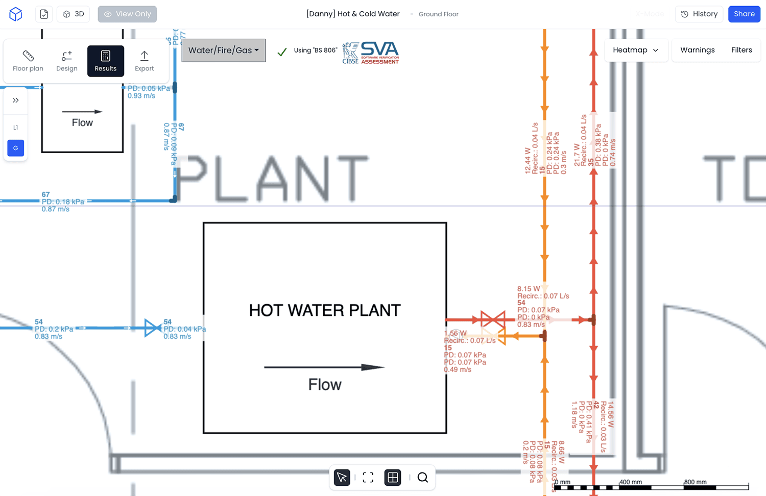
Once the system is connected, h2x can calculate the hydraulic and thermal results from the design.
Rather than treating these as separate calculations, the results remain connected to the system layout. If the pipework or project parameters change, the updated design can be reviewed without rebuilding the calculation process from the beginning.
Depending on the system and project setup, results can include:
| Result | What it shows |
|---|---|
| Return system duty flow | The circulation flow required by the return system |
| Return system pressure loss | The hydraulic resistance that affects the required pump duty |
| Return system heat loss | Heat lost from the circulating distribution pipework |
| Balancing valve Kv | The calculated valve coefficient used to balance the circulation circuit |
| Pipe peak flow | The peak design flow through a section of pipework |
| Pipe return flow | The circulation flow through the return pipework |
| Pipe diameter | The calculated or selected pipe size |
| Pipe velocity | The water velocity at the calculated design flow |
| Loading units | The connected fixture demand used in the design |
| Fixture pressure | Static and dynamic pressure conditions at connected fixtures |
| Dead leg results | Information relating to non-circulating branches serving individual outlets |
These results allow the designer to review the complete system rather than looking at pipe sizing, heat loss and circulation duty in isolation.
6. Check the Recirculation Pump Duty
The return system flow and pressure loss help establish the duty required from the recirculation pump.
Pump selection should consider both values together:
- Flow: The circulation flow the system requires
- Head: The resistance the pump needs to overcome through the hydraulically most demanding circulation route
Together, these form the pump duty point.
A manufacturer pump curve can then be used to check whether a proposed pump can provide the required flow at the calculated head.
The detailed calculation process is covered in our guide to recirculation pump duty and selection.
7. Review Changes as the Design Develops
Hot water designs rarely remain unchanged from the first layout.
A fixture may move. A pipe route may become longer. The insulation specification can change, or another branch may be added to the system.
Because the calculations remain connected to the layout in h2x, designers can review the impact of those changes within the same project rather than manually checking multiple calculation sheets against an updated drawing.
This is particularly useful on larger systems where a relatively small layout change can affect several parts of the hydraulic design.
For a broader engineering checklist covering layout, circulation flow, pressure loss, balancing and pump selection, see our six hot water system design considerations for recirculation.
For high-rise projects, there are additional considerations around static pressure, PRVs, balancing and pressure zoning. Our guide to hot water recirculation design for high-rise buildings covers these separately.
Design Hot Water Recirculation Systems in One Workflow
The main advantage of designing the system in h2x is that the layout and calculations remain connected.
Instead of completing the drawing first and then rebuilding the same system in separate calculation sheets, designers can develop the layout while reviewing pipe sizes, circulation flow, pressure loss, heat loss and balancing results as the project changes.
Design hot water systems faster in h2x
Build your system layout while reviewing pipe sizing, circulation flow, pressure loss and balancing in one connected workflow.
Frequently Asked Questions
How Do You Design a Hot Water Recirculation System?
Start by defining the project parameters and hot water source, then draw the distribution and return pipework. Add the fixtures and valves before calculating circulation flow, pressure loss, pipe sizing and balancing requirements. The final pump duty should be based on the required return flow and pump head.
What Calculations Are Needed for a Hot Water Recirculation System?
Typical calculations include pipe heat loss, required return flow, pressure loss, pipe sizing, velocity, balancing valve requirements and recirculation pump duty. The exact calculations depend on the project and system arrangement.
How Is Hot Water Recirculation Flow Calculated?
The required circulation flow is commonly based on the heat loss from the relevant hot water distribution pipework and the selected temperature difference between flow and return. A smaller temperature difference requires a higher circulation flow for the same heat loss.
Why Do Hot Water Recirculation Systems Need Balancing?
Different circulation circuits can have different hydraulic resistance. Without balancing, lower-resistance circuits may receive disproportionate flow while other parts of the system receive too little. Balancing valves add controlled resistance so the required flow can be distributed between circuits.
Can h2x Calculate Recirculation Pump Duty?
h2x can calculate return system flow and pressure loss as part of the hot water design workflow. These values can then be used to establish the required recirculation pump duty and review suitable pump performance.
Does h2x Calculate Hot Water Pipe Sizes?
Yes. h2x can calculate and review pipe sizes alongside other results such as flow, velocity, pressure loss and fixture demand within the connected hot water system design.
Meet the author

Daniel Mousdell
Daniel Mousdell is the Founding Marketer at h2x, where he creates technical content and resources for HVAC and MEP engineers. Outside of work, he runs LilWayneHQ.
Article published: June 14, 2021
Last updated: October 8, 2026
Technically reviewed by: Jonathan Mousdell, Mechanical Engineer and Co-founder at h2x