
How to Size a Circulation Pump for a Heating System
Check out how to calculate circulation pump flow and head, determine the index circuit and establish the pump duty point, with a worked heat pump example.
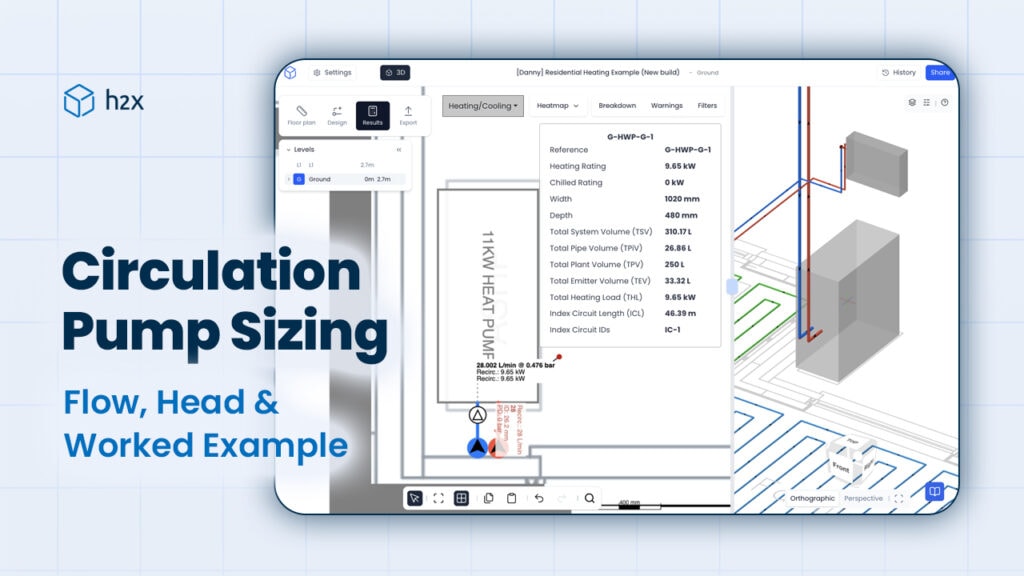
Correct circulation pump sizing starts with two values: the flow rate the heating system requires and the pump head needed to overcome resistance around the system.
A pump that cannot provide the required flow and head may prevent the system from operating as designed. Going too far in the other direction is not the answer either, as an oversized pump can create unnecessary flow, noise, differential pressure and energy use.
This guide explains how to calculate both parts of the pump duty point before working through an example for an 11 kW heat pump system.
Here, the focus is on circulation pumps used in closed heating and cooling systems. If you are designing a domestic hot water return loop, see our hot water recirculation pump sizing and selection guide instead.
How Circulation Pump Sizing Works
A circulation pump needs to move the required amount of water through the system while providing enough head to overcome the pressure losses created by pipes, valves, fittings, heat emitters and other components.
For most heating systems, circulation pump sizing comes down to two main calculations:
- Flow rate: How much water needs to circulate to transfer the required heat output at the selected temperature difference.
- Pump head: How much resistance the pump needs to overcome along the most hydraulically demanding flow path.
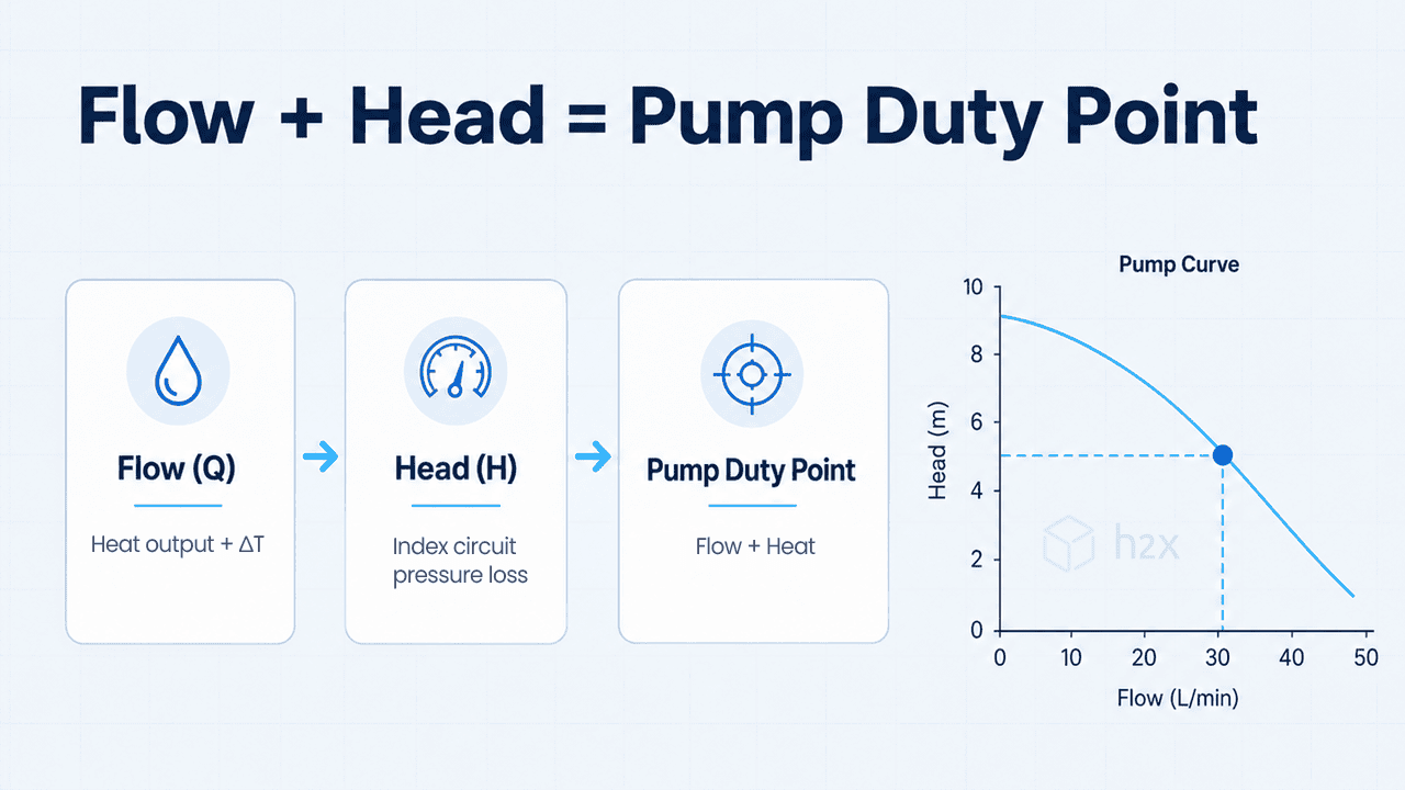
Together, these values form the pump duty point.
For example, specifying a pump based on flow alone is not enough. A pump may be capable of providing the required flow at a low head but unable to provide the same flow once connected to a system with greater resistance.
The calculated flow and head therefore need to be considered together when reviewing the manufacturer’s pump curve.
How to Calculate Circulation Pump Flow Rate
The required circulation flow depends on how much heat the system needs to transfer and the selected temperature difference between the flow and return.
The relationship is:
Heat Output = Mass Flow Rate × Specific Heat Capacity × ΔT
Rearranging this for flow gives:
Mass Flow Rate = Heat Output ÷ (Specific Heat Capacity × ΔT)
Where:
- Heat output is the required thermal output of the system
- Specific heat capacity depends on the circulating fluid
- ΔT is the selected temperature difference between flow and return
For water, a specific heat capacity of approximately 4.185 kJ/kg·K can be used for a simplified calculation.
The required fluid properties should be adjusted where the system contains glycol or another fluid mixture.
How ΔT Affects Circulation Flow
For the same heat output, a smaller ΔT requires a higher flow rate.
This is because less heat is transferred by each unit of water when the temperature difference between flow and return is reduced. More water therefore needs to circulate to transfer the same amount of heat.
For example, a heating system operating at a 5°C / 9°F ΔT will require more flow than the same system operating at a 10°C / 18°F ΔT.
The design ΔT should follow the heat source, emitter and system requirements rather than applying one value to every project.
Energy Saving Trust guidance also uses the relationship between heat output, mass flow, specific heat capacity and ΔT when describing heat pump system flow requirements.
Circulation Flow Rate Example
Assume a heat pump needs to deliver:
- Heat output = 11 kW
- Design ΔT = 5°C / 9°F
- Circulating fluid = water
- Specific heat capacity = approximately 4.185 kJ/kg·K
The required mass flow is:
11 kW ÷ (4.185 kJ/kg·K × 5°C) = 0.526 kg/s
With water density close to 1 kg/L under typical heating system conditions, this is approximately:
0.526 L/s, equivalent to 1.89 m³/h or 8.34 US gpm
The system therefore needs approximately 0.53 L/s (1.89 m³/h, or 8.34 US gpm) at the design condition.
The required heating output should come from the project design calculations. For more information, see our guide to calculating heat loss.
How to Calculate Circulation Pump Head
Once the required flow is known, the next step is to determine how much resistance the pump needs to overcome at that flow rate.
Pressure losses can occur through:
- Pipes
- Elbows and other fittings
- Isolation and balancing valves
- Control valves
- Heat emitters
- Heat exchangers
- The heat pump or heat source
- Other components in the circulation path
The required pump head is based on the most hydraulically demanding route through the system.
What Is the Index Circuit?
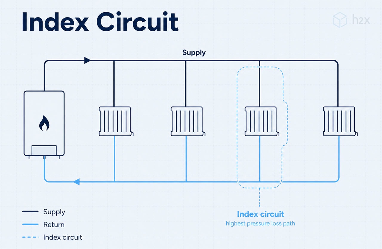
The hydraulically most demanding flow path is often called the index circuit.
This is the complete circuit with the greatest relevant pressure loss at the required operating condition. It is not necessarily the circuit that is physically furthest from the heat source.
Pressure losses through separate parallel circuits should not simply be added together. Instead, calculate the pressure loss along each complete route and identify the circuit that determines the required pump head.
This distinction matters in systems with several branches because the longest circuit may use larger pipes or contain fewer restrictive components than a shorter route.
Calculating Pipe Pressure Loss
Pressure loss through straight pipe can be calculated using the Darcy-Weisbach relationship:
ΔP = f × (L ÷ D) × (ρv² ÷ 2)
Where:
- ΔP = pressure loss
- f = Darcy friction factor
- L = pipe length
- D = internal pipe diameter
- ρ = fluid density
- v = fluid velocity
As flow increases through a given pipe size, velocity and pressure loss generally increase.
Rather than applying one universal maximum velocity or pressure loss rate, designers should use the requirements appropriate to the pipe material, system, equipment, noise criteria and applicable project standards.
You can also use our free pressure drop calculator to calculate pipe pressure loss.
Calculating Valve and Fitting Pressure Loss
Valves and fittings can also create a significant part of the total system resistance.
Where a component uses a resistance coefficient or K-value, the pressure loss can be calculated using:
ΔP = K × (ρv² ÷ 2)
Manufacturer data should be used where available, particularly for components such as:
- Control valves
- Heat emitters
- Balancing valves
- Heat exchangers
- Heat pumps
This is preferable to assuming one fixed pressure loss for a particular component type because the actual resistance can vary substantially between products.
Converting Pressure Loss to Pump Head
Pump curves normally express hydraulic performance using flow and head rather than system pressure loss alone.
If the index circuit calculation produces a pressure differential, it can be converted into head using:
Head = Pressure Difference ÷ (Fluid Density × Gravitational Acceleration)
For water:
10 kPa ≈ 1.02 m of head
In US customary units:
1 psi ≈ 2.31 ft of head
The required flow and calculated head then form the pump duty point.
Does Building Height Affect Circulation Pump Head?
In a closed heating or cooling loop, the full vertical height of the building is generally not added to the circulation pump head.
Water that rises through the system also falls again as it completes the closed circuit. The circulation pump therefore primarily needs to overcome friction and component pressure losses around the loop.
This is different from the static pressure needed to fill the system and establish the required operating pressure.
What Happens if a Circulation Pump Is the Wrong Size?
Choosing a larger pump does not automatically make a heating system perform better. The aim is to select a pump that can meet the required duty without creating unnecessary flow or differential pressure.
Undersized Circulation Pump
If a pump cannot provide the required flow at the calculated head, parts of the heating system may receive insufficient circulation.
Depending on the system, this can result in:
- Insufficient flow through the heat source
- Reduced heat transfer
- Heat emitters failing to provide their intended output
- A larger-than-designed flow to return temperature difference
- Heat pump flow alarms or operating issues where minimum flow requirements are not met
The exact result depends on the system configuration and equipment controls.
Oversized Circulation Pump
An oversized pump can provide more flow or differential pressure than the system needs.
Potential consequences include:
- Higher pump energy use
- Excessive pipe velocity
- Flow noise
- Greater differential pressure across valves and other components
- Unnecessary operating cost
- Operation away from the pump’s intended efficient range
Pump sizing should therefore aim for the calculated system duty rather than simply selecting the model with the greatest available flow or head.
Circulation Pump Sizing Worked Example
This circulation pump sizing worked example brings the flow and head calculations together for an 11 kW heat pump system.
Assume the heating system has:
- Heat pump output = 11 kW
- Design ΔT = 5°C / 9°F
- Required flow = 0.526 L/s (1.89 m³/h, or 8.34 US gpm)
After identifying the index circuit, calculate the pressure losses through the pipes, heat emitter, valves, fittings and other components along that route.
For this worked example, assume the calculated losses are:
| Index circuit component | Pressure loss |
|---|---|
| Pipes | 14.838 kPa |
| Heat emitter and associated valve | 11.000 kPa |
| Valves and fittings | 0.622 kPa |
| Total index circuit pressure loss | 26.460 kPa |
A pressure loss of 26.46 kPa for water is approximately:
2.70 m of head (8.86 ft of head)
The required pump duty point is therefore approximately:
0.526 L/s at 2.70 m head
or:
1.89 m³/h at 2.70 m head
In US customary units:
8.34 US gpm at 8.86 ft head
These values can now be compared with manufacturer pump performance data.
How to Select a Circulation Pump From a Pump Curve
The final stage of circulation pump sizing is to compare the calculated duty point with the manufacturer’s pump curve. A pump curve shows the relationship between the flow a pump can provide and the corresponding head.
The two main values are:
- Q: Flow
- H: Head
The calculated system requirement creates a duty point that can be compared with the manufacturer’s Q-H curve.
For the worked example, the pump needs to provide approximately:
1.89 m³/h at 2.70 m head
or:
8.34 US gpm at 8.86 ft head
A suitable pump needs to provide that combination of flow and head within its permitted operating range.
Grundfos explains how pump curves combine flow and head and how the system requirement forms the duty point used during pump selection.
Pump selection should also take account of factors such as:
- Manufacturer operating limits
- Efficiency at the required duty
- Variable speed control where applicable
- Minimum and maximum flow requirements
- Fluid temperature and composition
- System control strategy
The objective is not simply to find a curve above the required duty point. The selected pump should operate appropriately across the conditions expected in the real system.
Calculating Circulation Pump Duty in h2x
Circulation pump sizing becomes more time-consuming as the heating system grows. A change to pipe size, system flow or layout can affect velocity, pressure loss and ultimately the required pump duty.
h2x connects those calculations to the heating system layout.
Designers can create the system and calculate results including:
- Heating flow rates
- Pipe sizes
- Pipe velocity
- Component pressure losses
- Pipe pressure loss
- Index circuit pressure loss
- Circulation pump duty
This makes it easier to see how changes to the system affect the hydraulic calculations without manually updating separate drawings and spreadsheets.
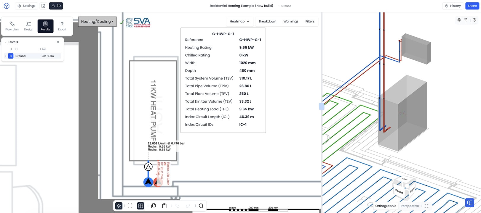
The calculated duty can then be used when reviewing manufacturer pump curves and selecting equipment for the project.
Calculate circulation pump duty faster in h2x
Design your heating system in one connected workflow, with system flow, pipe sizing and pump duty calculated as you go.
Frequently Asked Questions
How Do You Size a Circulation Pump?
Size a circulation pump by calculating the required system flow and pump head. The flow depends on the heat-transfer requirement and design ΔT, while the head comes from the pressure losses around the most hydraulically demanding circuit. Together, these values form the pump duty point.
How Do You Calculate Circulation Pump Flow Rate?
Calculate circulation flow from the required heat output, the specific heat capacity of the circulating fluid and the selected temperature difference between flow and return. For the same heat output, reducing the ΔT increases the required flow.
How Do You Calculate Circulation Pump Head?
Calculate the pressure losses through pipes, fittings, valves, heat emitters and other components along the most hydraulically demanding circuit. Convert the resulting pressure differential into pump head before comparing the required duty with a manufacturer pump curve.
What Is the Index Circuit in a Heating System?
The index circuit is the complete flow path with the greatest relevant pressure loss at the design condition. It normally determines the required circulation pump head and is not necessarily the circuit located furthest from the heat source.
Does Building Height Affect Circulation Pump Head?
In a closed heating or cooling loop, static building height is generally not added directly to the required circulation pump head. The pump primarily needs to overcome friction and component pressure losses around the closed circuit.
Can a Circulation Pump Be Oversized?
Yes. A pump that provides substantially more flow or head than the system requires can increase electrical consumption, pipe velocity, noise and differential pressure. The selected pump should suit the calculated duty and expected operating range.
What Is the Difference Between a Circulation Pump and a Hot Water Recirculation Pump?
A circulation pump in a heating or cooling system moves fluid around a closed circuit to transfer heat between the heat source and the system. By contrast, a domestic hot water recirculation pump circulates heated water through a return loop so hot water remains available closer to outlets. Although both pumps are selected using flow and head, the system requirements and sizing calculations serve different purposes.
Meet the author

Daniel Mousdell
Daniel Mousdell is the Founding Marketer at h2x, where he creates technical content and resources for HVAC and MEP engineers. Outside of work, he runs LilWayneHQ.
Article published: June 26, 2023
Last updated: October 8, 2026
Technically reviewed by: Jonathan Mousdell, Mechanical Engineer and Co-founder at h2x