Recirculation Pumps
A complete guide to sizing Recirculation Pumps. Learn the calculations, know when they are required, and ensure they are installed correctly.
Download your free PDF of this article below.
What are recirculation pumps?
A recirculation pump is a type of pump that is used to circulate water, usually in a closed-loop system like a 'hot water recirculation system'.
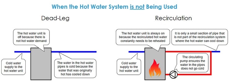
Have you ever waited a long time for hot water to come out of the tap? It is likely that the long wait is because the building has a dead-leg hot water system instead of a recirculation system.
A hot water recirculation system (with hot water recirculating pumps) prevents this long wait by constantly circulating hot water and minimises the length of the dead leg.
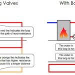
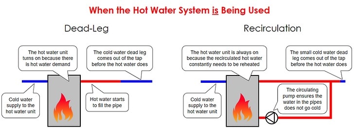
Below is a simple visual comparison of a dead-leg and hot water pump recirculating system:
Do you need a recirculation pump?
Waiting for hot water is tolerable in some circumstances, but a single dead-leg system in a large building is not fit for purpose.
In large buildings, a hot water recirculation system has a lot of benefits, mainly:
- They prevent you from waiting a long time for the hot water to come out of the taps
- They prevent you from wasting cold water whilst waiting for the hot water
Providing multiple dead-leg systems is another common way to provide hot water in a high-rise building. They are especially common in apartment buildings, where every apartment has its own hot water plant.
A simple diagram of dead-leg systems in a large building is below:
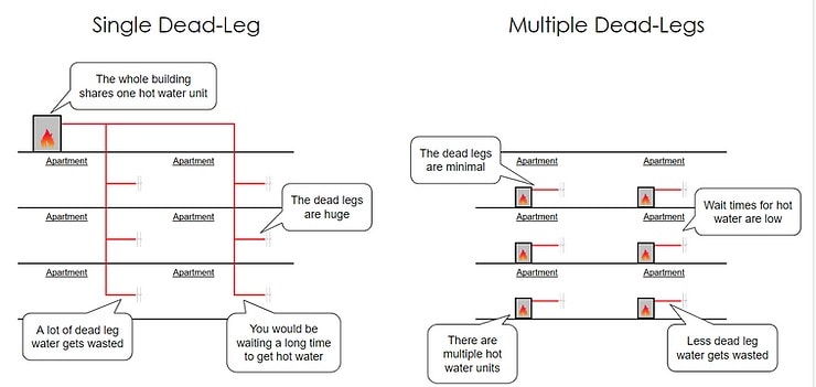
Multiple dead-leg systems achieve the same benefits as the recirculation system and are a much simpler design.
However, the main drawback is the cost associated with the additional hot water plant.
Where minimising cost is a big factor in the project design, which it normally is, then a recirculation pump in a closed-loop system is the best way to proceed.
Click here to learn more about designing hot water recirculation systems
The recirculation pump duty
There are two parts to the hot water recirculation pump duty:
- Flow rate
- The pump must be capable of overcoming the heat loss from all of the system's pipework
- The heat loss through the system is calculated in kW, which can be converted to a flow rate
- Pressure
- The pump must be capable of overcoming the pressure that is lost through the system's pipes, valves, and fittings at the heat loss flow rate in the 'index circuit' only
- The 'index circuit' is the circuit, always measured to and from the hot water plant, that has the most pressure loss when compared to other circuits. You do not need to combine the pressure loss through every circuit
- The pressure loss/gain from changes in height should not be included in the calculation. Because it is a closed-loop system, any changes in height are always equalled downstream in the system. What goes up must come down.
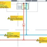
An example of the index circuit is shown below:
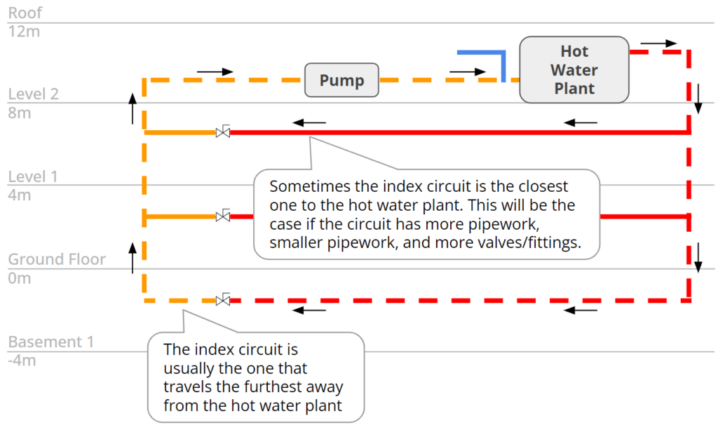
The pump duty is important as it informs selecting the correct recirculation pump for your application.
Recirculation pump flow rate:
To calculate the recirculation pump flow rate you need to know the following information:
- The length of each pipe diameter
- The system's 'delta T' (the difference between the flow and return system temperatures)
- The ambient air temperature (usually 21°C / 70F in buildings)
- The insulation diameter and thickness
- The air speed (usually 1m/s / 3ft/s in buildings)
With this information, you can undertake accurate calculations by following some complex physics equations.
Alternatively, insulation manufacturers usually have simpler heat loss data which you can use for your flow rate calculations.
Once you have the pipe heat loss, the below equation will turn the kW into a flow rate.
Recirculation pump flow rate equation:
Flow Rate = System Heat Loss (kW) / (Water Specific Heat Capacity (kJ/kg·K) * Delta T (°C))
Flow Rate = 5 kW / (4.185 kJ/kg·K * 5 °C)
Flow Rate = 5 kW / 20.925
Flow Rate = 0.239 L/s
Recirculation pump pressure:
To undertake detailed calculations on the pressure loss through the system's pipes, valves and fittings, learn the process in our pressure loss blog post.
Recirculation pump curves
Once you have calculated the recirculation pump duty, you need to select the best recirculation pump.
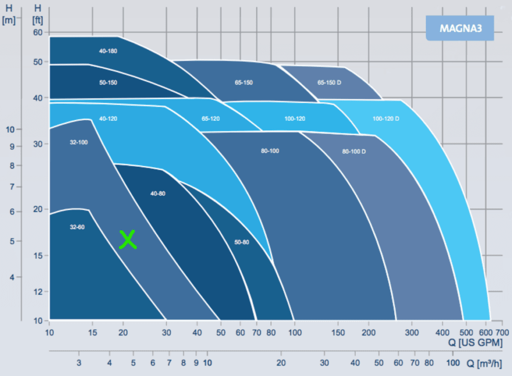
To check whether a pump is suitable for your design, you need to check its pump curve.
The pump curve indicates what flow and pressure the recirculation pump is capable of supplying.
Recirculation pump curve example
If the recirculation pump duty was 5mH @ 4.8m³/h, it would be outside of the '32-60' range on the below pump curve.
Therefore, that pump would not be capable of circulating the water to maintain the required temperature.
However, the pump duty is within the '32-100' range. Therefore, this pump would be a suitable selection.
What recirculation pump arrangements are available?
There are various arrangements of recirculation pumps available.
Before looking at the various arrangements, you should understand some common pump terminology:
- Duty Pump
- The duty pump is capable of supplying the system with the required flow and pressure under most scenarios
- Assist Pump
- The assist pump supplements the duty pump, sharing the load when the duty pump can't meet the required flow and pressure
- Standby Pump
- The standby pump is a backup to the duty pump, with the same pressure and flow capabilities.
- The duty and standby pumps switch over regularly to ensure there is equal wear on them
Whilst there are various configurations of these pump types, the most common are the two below:
- Duty
- This is suitable for projects where minimal cost is important and downtime due to maintenance is not an issue
- For example, this might be suitable for a house but it would terrible in a hospital
- Duty/Standby
- This is suitable for most projects as it is still relatively cost-effective
- The arrangement provides redundancy during periods of maintenance
What is the best location for the pump?
Recirculation pumps should be located where the return pipework connects to the hot water plant.
Because the recirculation pump's flow rate is usually lower than the system's peak flow rate, if it was on the flow pipework and a fixture was being used, the fixture would take the water.
Consequently, the water would not be able to recirculate back to the hot water plant.
Design communication
Whilst the recirculation pump is part of the plumbing system, it requires various members of the design team to allow for it in their own design.
If you do not communicate the various requirements to the rest of the team, they will not provide their services to it. This means there will be issues that need to be resolved later in the design stage, which will have significant consequences.
Electric requirements
Provide the electrical engineer with the power requirements and location of the recirculation pump.
The power supply will ensure the recirculation pump is able to operate
BMS requirements
Provide the mechanical (or sometimes electrical) engineer with the BMS requirements of the pump.
The BMS monitoring will inform the maintenance team of any issues with the pump by providing warnings to a central location.
Recirculation pump maintenance
Compared to other major components of a water system, recirculation pumps generally require minimal maintenance.
Maintenance is usually undertaken annually, which consists of:
- Visually inspect for any leakage
- Visually inspect the temperature gauges
- Visually inspect the pressure gauges
- Visually inspect the pump (impeller, seals, bearings, valves, volute) for signs of degradation
- Check the electrical components are in good condition
- Check that all BMS points are operating correctly
The pumps will need to be replaced eventually; their design life is around 15 years.
Temperature and pressure gauges
It is good practice to install temperature and pressure gauges in various locations around the hot water system.
Some example locations of where to locate temperature and pressure gauges are:
- On the incoming water supply to the hot water plant
- On the inlet to the hot water recirculation pump
- On the outlet of the hot water recirculation pump
- On each hot water circuit
The pressure gauges provide you with the ability to check the temperature and pressure in various locations around the building.
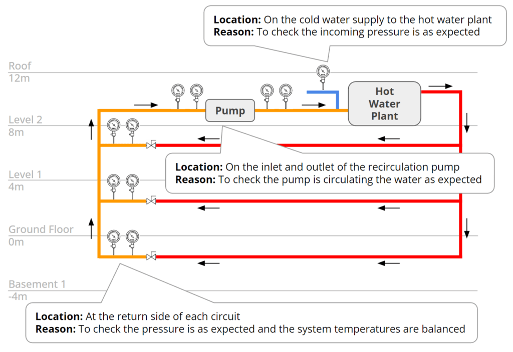
As you can see in the image above, if you found an unusual temperature or pressure reading at a point in the system, you could check the various gauges around the system to troubleshoot where the issue is coming from.
Without the gauges, it would be difficult, time-consuming, and intrusive to troubleshoot the problem.
This allows you to easily undertake fault finding and ensure the pump is operating as intended.

Did you know H2X’s design software makes the hot water calculation process much simpler?
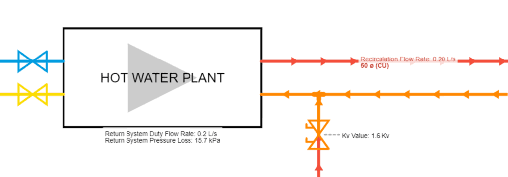
Simply draw the layout of the hot water system, set your design parameters, and all of the hot water recirculation calculations will be undertaken.

The detailed and accurate results include:
- Heat loss flow rates;
- Return pipe sizes;
- Recirculation pump duty (flow rate and pressure); and
- Balancing valve settings.
If you would like to learn more about H2X, we would love to hear from you.
You can request more information here or sign up for a 14-day free trial now.
h2x: All-In-One Tool for Calculating, Designing, Estimating, and Paperwork

What's in the Pipeline?
Get technical resources delivered to your inbox weekly!
Testimonials
What Installers Say
What Consultants Say
A game changer for the humble plumber. Incredible.
Brad Winkel
Director at Queenstown Plumbing
Brilliant, simple and easy to use. Game changer.
James Major
Director at Hubb
Big time game changer to the industry!
Viv Jude
Director at UHC
Incredible software! Super user-friendly and allows you to save so much time.
Devni Gamage
Engineer at DMA
h2x is great software, our company use it nearly every day. It is easy to use with direct conversion from h2x to Revit.
Callum Craig
Engineer at WDE
h2x is fantastic software. It is very easy to use and the ability to output to Revit is a fantastic time saver.
Joe Kirrane
Engineer at MEP


