Data Center Liquid Cooling Design for Direct-to-Chip Racks
How data center liquid cooling works, from CDUs and the three water loops to direct-to-chip flow rates, water temperatures and pipe sizing.
Data center liquid cooling removes server heat with water or coolant instead of air, usually through cold plates mounted on the chips. A coolant distribution unit (CDU) separates the rack loop from the building’s facility water. Each loop is then sized from its heat load and temperature rise.
The shift is happening because of rack density. In 2020, the average rack drew about 8.4 kW. A single GB200 NVL72 AI rack now draws 132 kW, and conventional air cooling can’t practically carry that much heat out of a cabinet. This guide covers when racks need liquid, how the loops fit together and the water temperatures they run at. Then a worked example sizes the pipework for a pod of AI racks.
Quick Answer: Data center liquid cooling carries heat from the chips in water or coolant, because air can’t move enough heat at today’s rack densities. Direct-to-chip cold plates feed a technology cooling loop, and a CDU passes that heat to the facility water. A smaller chilled water system still cools whatever stays on air.
What Is Data Center Liquid Cooling?
Data center liquid cooling is any system that takes heat away from IT equipment in a liquid rather than in air. The liquid picks up heat at or near the source, then carries it to plant that rejects it outdoors.
That’s because water is far better at this than air. At 68 °F (20 °C), water holds about 3,460 times as much heat per degree as the same volume of standard air. So a pipe can do the job of a very large duct.
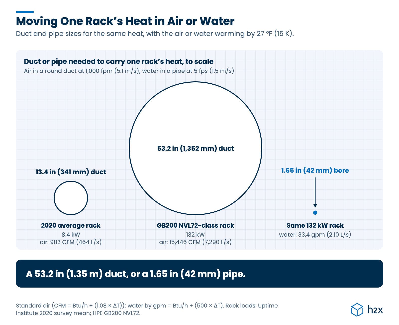
Here’s what that means for one rack, with the coolant or air warming by 27 °F (15 K):
| Rack | Heat load | Airflow needed | Round duct at 1,000 fpm (5.1 m/s) | Water flow needed | Pipe bore at 5 fps (1.5 m/s) |
|---|---|---|---|---|---|
| 2020 average rack, 8.4 kW | 28,662 Btu/h | 983 CFM (464 L/s) | 13.4 in (341 mm) | 2.1 gpm (0.13 L/s) | 0.42 in (11 mm) |
| GB200 NVL72-class rack, 132 kW | 450,403 Btu/h | 15,446 CFM (7,290 L/s) | 53.2 in (1,352 mm) | 33.4 gpm (2.10 L/s) | 1.65 in (42 mm) |
A 13.4 in (341 mm) duct per rack still fits under a raised floor. A 53.2 in (1,352 mm) duct per rack would be impractical in almost any data hall. Yet a pipe under 2 in (50 mm) across carries the same heat. These are theoretical sizes from the stated temperature rise and velocities, not a supplier’s duct or pipe spec.
When Does a Data Center Need Liquid Cooling?
Rack density decides the method. Vertiv puts the practical limit of air cooling at about 20 kW per rack, and says rear door heat exchangers extend that to between 20 and 80 kW. Above that, direct-to-chip cold plates usually take over.
| Rack generation | Typical heat per rack | Usual cooling |
|---|---|---|
| 2020 average enterprise rack | 8.4 kW (Uptime Institute survey mean) | Air, ideally with containment |
| H100-class GPU rack (4 systems at 10.2 kW) | About 40 kW | Air, often with rear door heat exchangers |
| GB200 NVL72 | 120 to 132 kW | Direct-to-chip, with some air |
Sources disagree on the GB200 figure: 132 kW is HPE’s published rack power, and other sources give 120 kW. Either way, the jump from one generation to the next is far bigger than any air system can follow.
Types of Data Center Liquid Cooling
Three approaches are in use, and they differ in how close the liquid gets to the chip.
- Rear door heat exchanger. A water coil replaces the back door of the rack. The servers still move their own air, but the coil catches the heat before it reaches the room. It suits racks from about 20 kW, and active doors with their own fans reach about 75 kW.
- Direct-to-chip cold plates. Coolant runs through metal plates clamped to the CPUs and GPUs, and quick-disconnect hoses link each server to a rack manifold. This is how GB200-class racks are cooled.
- Immersion. The servers sit in a tank of dielectric fluid. Single-phase immersion is in use. Two-phase immersion faces a fluid problem, because many of its fluids are fluorochemicals: 3M exited PFAS manufacturing, including those fluids, by the end of 2025.
Many direct-to-chip racks still need some air cooling. HPE’s figures for the GB200 NVL72 give 115 kW of the rack’s 132 kW to liquid and 17 kW to air, so about 87% goes to the cold plates. The rest comes from memory, drives, power supplies and network gear, which still rely on air.
The Three Water Loops in a Liquid-Cooled Data Center
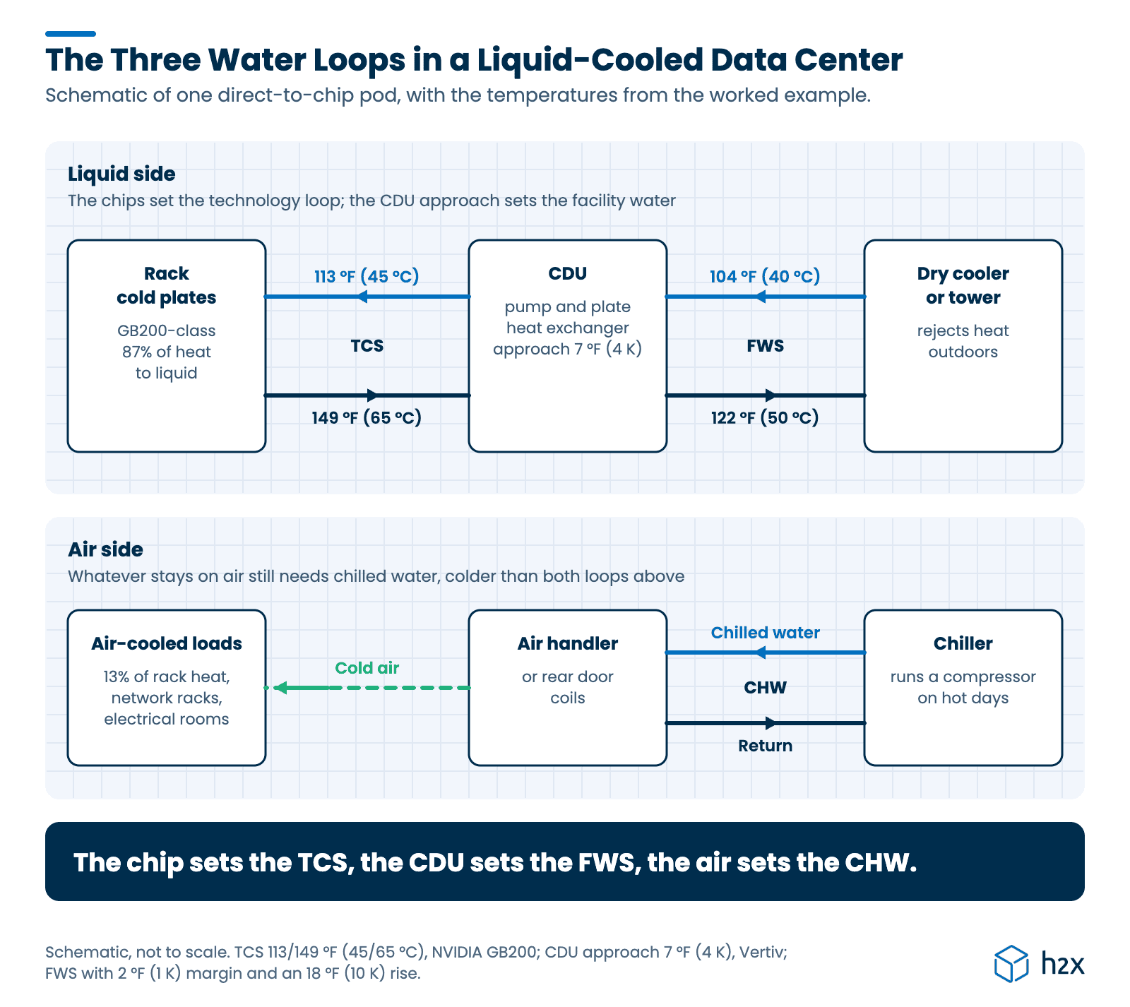
A liquid-cooled data hall runs up to three water systems, each at its own temperature:
| Loop | What it connects | Temperature set by |
|---|---|---|
| Technology cooling system (TCS) | CDU to the cold plates in each rack | The chip’s maximum inlet temperature |
| Facility water system (FWS) | CDU to the dry coolers, cooling towers or chillers | The TCS supply, less the CDU’s approach |
| Chilled water (CHW) | Chillers to the air handlers, electrical rooms and, depending on the design, rear doors | The air temperature the servers and rooms need |
ASHRAE TC 9.9 recommends a CDU as the boundary between the facility water and the technology loop. The two loops never mix. So the chip side keeps its own coolant, water treatment and pressure, while the facility side can run ordinary treated water.
What Does a CDU Do?
A CDU is a pump set, a plate heat exchanger and controls in one cabinet. It pumps coolant around the technology loop, controls its supply temperature and pressure, and passes the heat to the facility water through the plate.
A plate can’t move heat without a temperature difference across it, called the approach. So vendors quote it with each rating, typically 4 to 9 °F (2 to 5 K). Vertiv rates its CoolChip CDU 2300 at a 7 °F (4 K) approach, which this guide uses. So the facility water has to arrive at least 7 °F cooler than the coolant the chips receive.
Technology loops run treated water or a glycol mix, often PG25 (25% propylene glycol). The IT supplier specifies which. The Open Compute Project’s PG25 guidelines cover it, and ASHRAE doesn’t recommend a particular fluid.
PG25 holds less heat per gallon than water and flows more thickly, so check its properties before you size the TCS. Our guide to glycol in heating and cooling systems explains the trade-offs.
How Do You Size Data Center Liquid Cooling Pipework?
Size each loop from its own heat load and temperature rise, in four steps:
- Find the flow from the load: gpm = Btu/h ÷ (500 × ΔT) with ΔT in °F, or L/s = kW ÷ (4.18 × ΔT) with ΔT in K.
- Pick the smallest pipe that keeps velocity and friction within your limits.
- Work out the pressure loss on the critical circuit of each loop separately. The technology loop includes the cold plates, manifolds and the CDU’s chip side. The facility loop includes the CDU’s facility side and the heat rejection plant.
- Select the pump for that flow and total head.
That’s the same method as any closed water loop, and our hydronic piping design guide covers the limits in detail. What changes in a data center is the temperatures, and how much they drive everything after step one.
Rules of thumb in flow per kW, like 0.26 to 0.40 gpm (1 to 1.5 L/min) per kW, are really a temperature rise in disguise. For example, water at an 18 °F (10 K) rise needs 0.38 gpm (1.46 L/min) per kW. At 27 °F (15 K) it needs 0.26 gpm (0.97 L/min), and at 36 °F (20 K) only 0.19 gpm (0.73 L/min). So check the rise your IT supplier specifies before you use one.
Worked Example
An AI pod has eight GB200 NVL72-class racks at 132 kW each, served by one CDU. That’s 1,056 kW of IT load, or 3.60 million Btu/h. Using HPE’s split, 920 kW goes to liquid and 136 kW stays on air.
- Technology loop: NVIDIA’s GB200 design takes coolant at 113 °F (45 °C) and returns it at 149 °F (65 °C), a 36 °F (20 K) rise. So each rack needs 22.1 gpm (1.39 L/s), and the pod needs 177 gpm (11.2 L/s). That rise is from NVIDIA’s launch figures, so treat it as illustrative: the IT supplier’s coolant, temperature, flow and pressure drop specs govern.
- Facility water temperature: start from 113 °F (45 °C) at the chip. Take off the CDU’s rated 7 °F (4 K) approach and a further 2 °F (1 K) of margin, and the facility supply is 104 °F (40 °C). The real margin depends on the CDU you select.
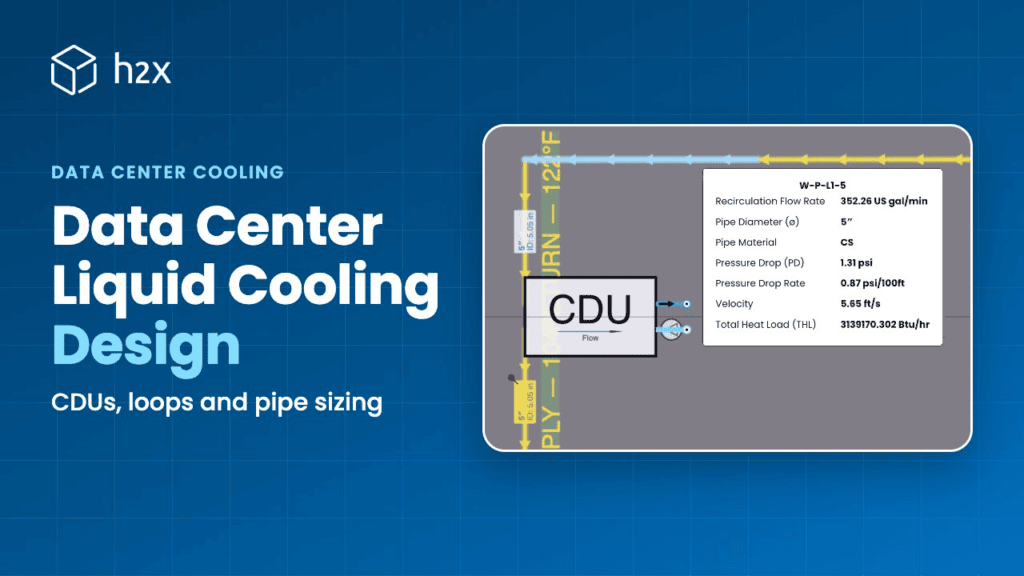
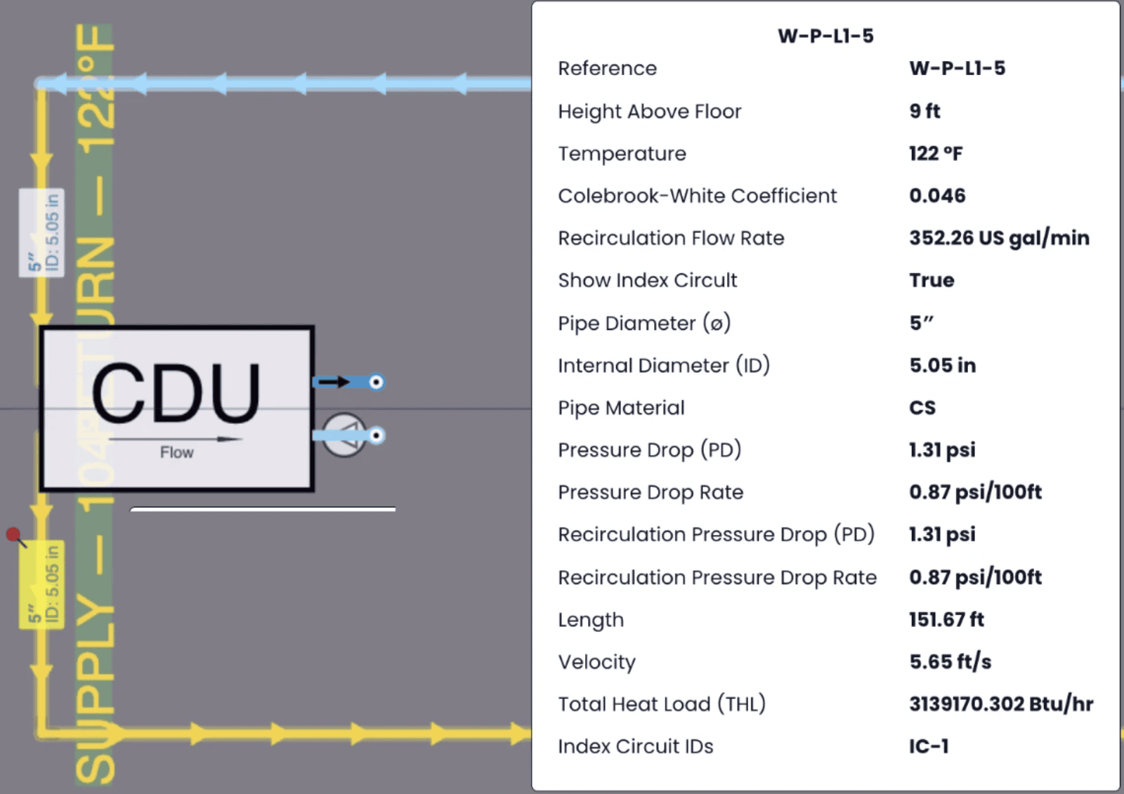
- Facility flow: at an 18 °F (10 K) rise, the CDU’s 920 kW (3.14 million Btu/h) needs 352 gpm (22.2 L/s).
- Pipe size: in Schedule 40 steel, 5 in (125 mm) carries it at 5.6 fps (1.72 m/s), losing 2.01 ft per 100 ft (196 Pa/m).
- Pipe friction: the longest circuit has 300 ft (91 m) of pipe, counting supply and return. Adding 50 to 100% for fittings gives 9.1 to 12.1 ft (2.8 to 3.7 m) of head, before the CDU, valves and heat rejection plant.
The example takes the coolant as water, at the mean temperature of each loop. A PG25 technology loop would need a higher flow, with a bigger pressure drop, than these figures show.
Why the Temperature Rise Matters
Now widen the facility loop from an 18 °F (10 K) to a 27 °F (15 K) rise. The return water then comes back at 131 °F (55 °C) instead of 122 °F (50 °C). The flow falls to 235 gpm (14.8 L/s), 67% of the first case. That opens two options:
| Facility loop | Flow | Main | Friction | Hydraulic power for pipe friction, 300 ft (91 m) plus 50% |
|---|---|---|---|---|
| 18 °F (10 K) rise | 352 gpm (22.2 L/s) | 5 in (125 mm) | 2.01 ft/100 ft (196 Pa/m) | 0.80 hp (0.60 kW) |
| 27 °F (15 K) rise, smaller main | 235 gpm (14.8 L/s) | 4 in (100 mm) | 2.90 ft/100 ft (281 Pa/m) | 0.77 hp (0.57 kW) |
| 27 °F (15 K) rise, same main | 235 gpm (14.8 L/s) | 5 in (125 mm) | 0.93 ft/100 ft (90 Pa/m) | 0.24 hp (0.18 kW) |
So a wider rise gives you a choice. You can fit a smaller, cheaper main at about the same pumping power. Or you can keep the main and cut its pumping power by about 70%, or settle somewhere between. These figures cover pipe friction only, not the CDU, valves, plant or pump efficiency.
Two limits apply. The IT equipment’s limits cap how far you can go, because the facility return has to stay below the coolant leaving the racks. And a hotter facility return narrows the temperature difference across the CDU’s plate, so check the CDU can still pass 920 kW at the lower flow.
What Water Temperature Does Data Center Liquid Cooling Need?
Work backwards from the chip. NVIDIA designs its MGX racks to take coolant at up to 113 °F (45 °C). Subtract the CDU approach and a margin, and the facility water can be as warm as about 104 °F (40 °C), as in the worked example.
Then check it against the weather. A dry cooler makes water a few degrees above the outdoor air temperature, about 9 °F (5 K) according to Airedale, though it varies with the selection. So the warmer the water the IT equipment accepts, the more of the year a dry cooler can do the job without a compressor.
ASHRAE TC 9.9 sorts liquid-cooled IT equipment into W classes by the warmest facility water it accepts. Its Thermal Guidelines, 5th edition (2021), renamed them after their temperature limits:
| Class | Warmest facility supply water | Dry cooler can do the job below about |
|---|---|---|
| W17 | 63 °F (17 °C) | 54 °F (12 °C) |
| W27 | 81 °F (27 °C) | 72 °F (22 °C) |
| W32 | 90 °F (32 °C) | 81 °F (27 °C) |
| W40 | 104 °F (40 °C) | 95 °F (35 °C) |
| W45 | 113 °F (45 °C) | 104 °F (40 °C) |
| W+ | Above 113 °F (45 °C) | Above 104 °F (40 °C) |
The class limits come from the Open Compute Project’s CDU test methodology paper, citing ASHRAE. The dry cooler column assumes the 9 °F (5 K) approach above.
The class is usually fixed when the IT equipment is bought, often before a mechanical engineer joins the project. It’s worth asking for early, because it decides how much compressor plant the facility loop needs.
Why a Liquid-Cooled Data Center Still Needs Chilled Water
Even so, most liquid-cooled data halls still need a separate system for the heat that stays on air. In the worked example, 136 kW of the pod’s 1,056 kW stays on air, from memory, drives, power supplies and switches. Network and storage racks are often air-cooled entirely, and so are the electrical rooms with their UPS systems and switchgear.
That air has to reach the servers within ASHRAE’s recommended inlet range of 64.4 to 80.6 °F (18 to 27 °C). The newer high-density class, H1, narrows it to 64.4 to 71.6 °F (18 to 22 °C). So the water serving the air side must be much colder than the 104 °F (40 °C) facility water. In most climates that means chilled water, or direct expansion cooling, with a compressor running on hot days.
The share left on air is shrinking. NVIDIA says its Vera Rubin MGX racks can be fully liquid-cooled. But the electrical rooms and network gear still need cooling of their own.
Ride-Through and Thermal Storage
A liquid-cooled rack has very little thermal mass, so it has seconds rather than minutes when cooling stops. Vertiv notes that a high-power chip can reach its thermal limit in under a second once coolant stops. Grundfos, citing ASHRAE’s liquid cooling technical bulletin, puts the time from a CDU pump failure to processor throttling at as little as 23 seconds.
A standby generator takes about 10 seconds to start under NFPA 110 Type 10, and chillers can take minutes to restart. So the technology loop pumps and CDU controls usually go on UPS, and many designs add a thermal store. ASHRAE’s bulletin also calls for more thermal inertia, and for active redundancy during changeover to backup systems. Uptime Institute recommends continuous cooling above 4 kW per rack, whatever the Tier.
Size a store from V = P × t ÷ (ρ × cp × ΔT). For 1 MW, take water at 104 °F (40 °C) with an 18 °F (10 K) usable swing. That’s about 764 gal (2.9 m³) for 2 minutes, and 5,733 gal (21.7 m³) for 15 minutes. Put the store on the side of the CDU it protects: on the technology loop for the chips, or on the facility loop for a plant restart.
Common Data Center Liquid Cooling Mistakes
- Taking a flow-per-kW rule without the temperature rise. 0.4 gpm (1.5 L/min) per kW is an 18 °F (10 K) rise, so at 36 °F (20 K) the chips need half that.
- Forgetting the CDU approach. The facility water must be about 7 °F (4 K) cooler than the technology loop supply. So the approach caps how warm the facility loop can run.
- Sizing the technology loop with water properties. At the same load, PG25 needs a higher flow than water, and its pressure drop is bigger.
- Leaving out the air side. The air-cooled share, the network racks and the electrical rooms still need cooling, usually from chilled water.
- Pumps without UPS. A liquid-cooled rack can’t ride out a generator start with its pumps stopped.
How h2x Helps with Data Center Liquid Cooling Design
h2x engineering software lays out and sizes the facility water and chilled water pipework in one model. Each loop gets the fluid properties for its own temperature, and friction comes from Darcy-Weisbach with the Colebrook-White friction factor.
First, set the limits once in Settings > Methods. The Pipe Sizing Method works to a velocity cap, a pressure drop cap, or both. The Pressure Loss Method can add each component’s own loss, such as a CDU’s plate.
You can configure a CDU between the facility and technology loops, and the fluids include ethylene glycol as well as water. Try a different temperature rise or rack load, and the flows and sizes update. So you can compare options like the ones in the table above on your own layout.
Built in h2x, the worked example’s pod gives the same answer. The main carries 352 gpm (22.2 L/s) in 5 in (125 mm) pipe at 5.65 fps (1.72 m/s).
h2x’s heating and cooling water calculations are verified by CIBSE and are aligned with ASHRAE methods.
Key Takeaways
Data center liquid cooling can use three loops at three temperatures. The CDU passes heat from the technology loop to the facility water, while a separate chilled water system handles the air-cooled loads.
- Density decides the method: air gets hard above about 20 kW per rack, rear doors can reach roughly 80 kW, and the densest AI racks use direct-to-chip.
- Flow comes from the temperature rise: gpm = Btu/h ÷ (500 × ΔT), so a flow-per-kW rule hides a rise.
- A wider facility rise cuts the flow, which allows a smaller main, less pumping, or a balance of both.
- The W class sets how much of the year a dry cooler can work without a compressor.
- Air cooling stays, for the air-cooled share and the electrical rooms, usually on chilled water.
FAQ
What is direct-to-chip liquid cooling?
Direct-to-chip cooling pumps coolant through metal cold plates mounted on the CPUs and GPUs, so the heat goes straight into the liquid. A CDU circulates the coolant and passes the heat to the building’s facility water. In a GB200 NVL72 rack, about 87% of the heat goes to liquid.
What does a CDU do in a data center?
A coolant distribution unit pumps coolant around the technology loop and passes its heat to the facility water through a plate heat exchanger. It keeps the two loops apart, so the chip side keeps its own coolant, treatment and pressure. Vendor approach temperatures typically run from 4 to 9 °F (2 to 5 K).
How much coolant flow does a direct-to-chip rack need?
It depends on the temperature rise. With water, an 18 °F (10 K) rise needs about 0.38 gpm (1.46 L/min) per kW, and a 36 °F (20 K) rise needs half that. A 132 kW GB200 NVL72-class rack with 115 kW on liquid needs about 22 gpm (1.4 L/s) at a 36 °F (20 K) rise.
What water temperature does direct-to-chip cooling need?
Work back from the chip’s inlet limit. NVIDIA designs its MGX racks for coolant at up to 113 °F (45 °C). Subtract the CDU approach and a margin, and the facility water can run at about 104 °F (40 °C), warm enough for dry coolers most of the year.
What is an ASHRAE W class?
An ASHRAE W class sets the warmest facility water that liquid-cooled IT equipment accepts. The classes are W17, W27, W32, W40, W45 and W+, named after their limits in °C. So a higher class lets dry coolers handle more of the year without a compressor.
Do liquid-cooled data centers still need chillers?
Usually, yes. Some heat in most direct-to-chip racks stays on air, about 13% in a GB200 NVL72. Network racks and electrical rooms are usually air-cooled too. That air needs water much colder than the chip loop, so most sites keep chillers or direct expansion units for it.
Model Every Cooling Loop at Its Own Temperature
h2x sizes facility water and chilled water pipework against the velocity and pressure drop caps you set. Change a rack load or a temperature rise, and every flow and pipe size updates with it.
Meet the author

Daniel Mousdell
Daniel Mousdell is the Founding Marketer at h2x, where he creates technical content and resources for HVAC and MEP engineers. Outside of work, he runs LilWayneHQ.
Article published: October 19, 2026
Last updated: October 19, 2026