Hydronic Piping Design Guide for Layouts and Pipe Sizing
A hydronic piping design guide to layouts, direct and reverse return, primary-secondary piping and pipe sizing, with worked examples for heating and chilled water.
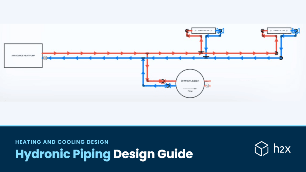
Hydronic piping is the network of pipes, pumps and valves that carries hot or chilled water from a boiler, heat pump or chiller to the emitters and back. Designing it means choosing a layout, then sizing each pipe for its flow so velocity and friction stay within limits.
Get either step wrong and the system shows it. A poor layout leaves rooms far from the plant short of flow. An undersized pipe is noisy and needs a bigger pump, while an oversized one costs more to buy and install. This guide covers the common layouts, how to size each pipe and two worked examples, one for heating water and one for chilled water.
Quick Answer: Hydronic piping carries heated or chilled water between the plant and the emitters in a closed loop. Pick a layout first: direct return, reverse return or primary-secondary. Then find each section’s flow from its load (gpm = Btu/h ÷ (500 × ΔT)), and size each pipe so velocity and friction stay within your limits.
What Is Hydronic Piping?
A hydronic system moves heat with water instead of air. In heating, a boiler or heat pump warms the water, and radiators, fan coils or radiant floors release the heat. In cooling, a chiller supplies chilled water to fan coils and air handling unit coils, which take heat out of the air.
Most hydronic systems are closed loops: the same water circulates, sealed from the atmosphere. Besides the plant, pumps and emitters, a closed loop needs an expansion tank for the water’s change in volume. It also needs air separation, and valves to isolate and balance each circuit.
Where the expansion tank connects matters. ASHRAE’s hydronic chapter notes that the pressure at the tank connection doesn’t change when the pump starts. With the tank on the pump’s suction side, the pump adds its pressure to the system. With the tank on the discharge side, the pressure on the suction side drops by the same amount instead.
The piping ties all of that together. Its layout decides how evenly water reaches each emitter, and its sizes decide how much pump head the system needs.
Hydronic Piping Layouts
The hydronic heating and cooling chapter of the ASHRAE Handbook, HVAC Systems and Equipment (Chapter 13) describes the common layouts. Each trades piping cost against control and balance. The first four describe how water reaches the emitters. Primary-secondary describes how the pump circuits connect, so its zones can still use direct or reverse return:
| Layout | How it works | Best for | Trade-off |
|---|---|---|---|
| Series loop | One pipe runs through every emitter in turn | Small residential heating | Lowest piping cost and a large temperature drop, but you can’t control the emitters separately |
| One-pipe (diverting tee) | A special tee diverts part of the main’s flow through each emitter | Small heating systems that need some zone control | Downstream emitters get cooler water, the diverting tees add pressure loss, and each unit usually needs a manual air vent |
| Two-pipe direct return | Separate supply and return mains; water returns by the shortest path | Most commercial systems, with balancing valves | Circuits near the plant can get more flow than far ones unless you balance them |
| Two-pipe reverse return | The first emitter supplied is the last returned, so every circuit has a similar length | Systems with many similar terminals | Closer to self-balancing when terminals are similar, but uses more pipe and may still need balancing valves |
| Primary-secondary | Plant and zone circuits each have their own pump and connect through a short, low-loss common pipe or closely spaced tees | Systems that need independent pumping, different flow rates or different water temperatures | More pumps and controls, and when the two flows differ, water mixes in the common pipe and shifts the supply temperature |
Direct Return vs Reverse Return
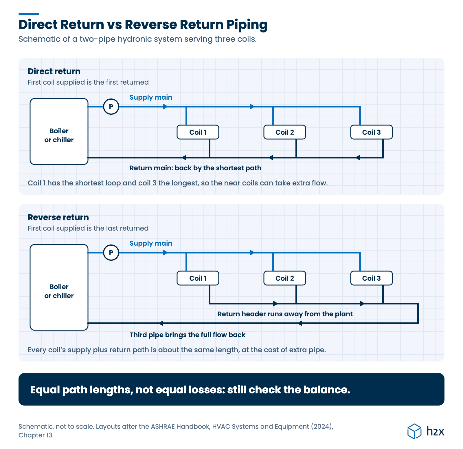
In a direct return system, the supply and return paths through the near circuits are shorter than through the far ones. So the near circuits see less pressure loss and can take more than their share of flow. Balancing valves fix that by adding resistance to the short circuits.
Reverse return evens out the paths instead. The first circuit to get supply water is the last to return it. So every circuit has nearly the same total pipe length. That makes it closer to self-balancing when the terminals are similar. But equal pipe lengths don’t mean equal pressure losses: coils, control valves and pipe sizes still differ, so check the balance anyway. The price is usually extra pipe. And a reverse return main that dead-ends needs a third pipe to bring the full flow back.
Primary-Secondary Piping
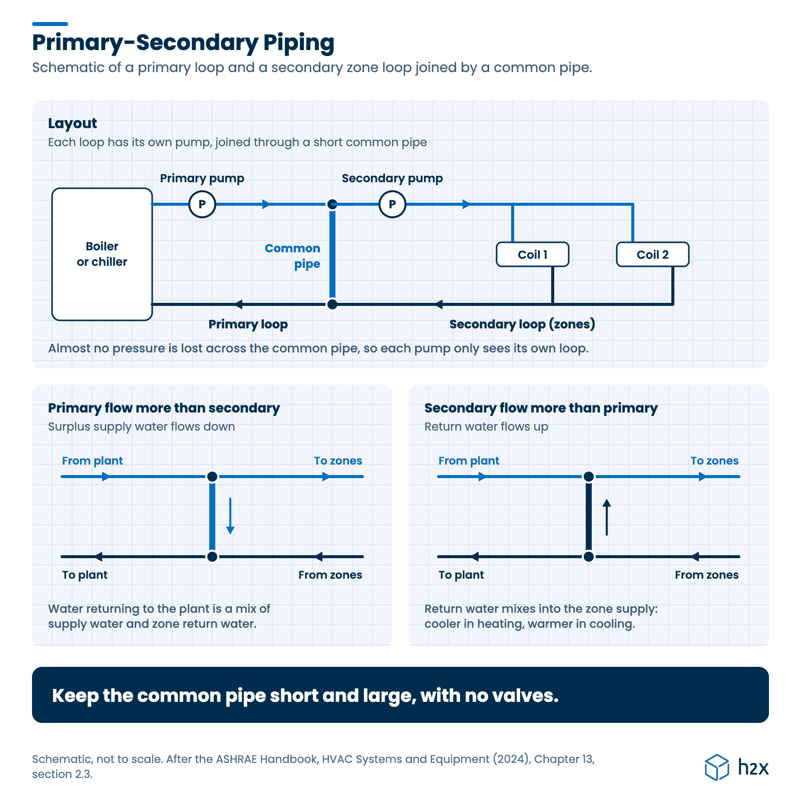
Primary-secondary piping, also called compound pumping, splits the system into a primary loop through the plant and secondary loops for the zones. The loops connect through a short common pipe, often formed by two closely spaced tees. Because almost no pressure is lost across the common pipe, each pump only sees its own loop.
ASHRAE’s chapter sets the rules for the common pipe. Keep it as short and as large in diameter as practical, to keep its pressure loss low. But not so short and large that it acts like a tank: it needs enough length to stop unwanted recirculation. And never put a valve or check valve in it. Done well, compound pumping can reduce the size and cost of the distribution system.
Watch the flows on each side. ASHRAE notes that when the two pumps’ flows differ, water flows through the common pipe. When the secondary loops draw more than the primary loop supplies, return water flows back through the common pipe and mixes into the supply. Then the zones see a lower supply temperature in heating, or a higher one in cooling.
Hydronic Piping Materials
Copper and steel are the traditional hydronic pipe materials. This guide’s charts cover Type L copper from ½ to 4 in (15 to 100 mm). They also cover Schedule 40 carbon steel from 2 to 8 in (50 to 200 mm).
Plastics are now common too. The Plastics Pipe Institute lists certain CPVC, HDPE, PEX, PEX-AL-PEX, PE-RT and PP pipe for hydronic distribution. But it doesn’t recommend HDPE for hot water. It notes that model codes, including the IMC and IRC, approve plastic pipe for hydronics. PEX, PE-RT and PEX-AL-PEX are the usual choices for radiant heating and cooling. Several codes require oxygen barrier tubing there. Plastic pipe isn’t intended for steam.
Material also sets the pipe’s roughness and its internal diameter, so the same nominal size carries a different flow in copper, steel and plastic.
How Do You Size Hydronic Piping?
You size hydronic pipe in four steps:
- Find each section’s flow from the load it serves.
- Start from the smallest pipe that might carry it.
- Check the velocity and the friction loss against your limits.
- If either check fails, step up a size and check again.
Flow from the Load
For water, the flow you need depends on the heat load and the temperature difference between supply and return:
gpm = q / (500 × ΔT)
Here q is the load in Btu/h and ΔT is the supply to return temperature difference in °F. The 500 comes from 8.33 lb per gallon × 60 minutes per hour × 1 Btu per lb·°F. So it’s approximately correct for water near 60 °F (16 °C).
ASHRAE’s chapter agrees: 1 gpm (0.063 L/s) carries 10,000 Btu/h (2.9 kW) at a 20 °F (11 K) difference. In metric, the same relationship is:
L/s = kW / (4.18 × ΔT)
Here ΔT is in K, and the 4.18 is for water near 68 °F (20 °C).
Real water is lighter when hot, so the factor drifts with temperature. Use the mean of the supply and return temperatures: the factor is about 489 for water averaging 170 °F (77 °C), and 502 at 50 °F (10 °C). So using 500 understates a hot water flow by about 2%. The metric factor drifts the same way, to about 4.08 at 170 °F (77 °C).
Velocity and Friction Limits
The pipe chapter of the 2021 ASHRAE Handbook, Fundamentals (Chapter 22, section 3) gives general design guidance for HVAC water piping:
- Friction: design for 1 to 4 ft per 100 ft (100 to 400 Pa/m) of friction head. The typical mean is 2.5 ft per 100 ft (250 Pa/m).
- Velocity: keep 2 in (50 mm) pipe and smaller at 4 fps (1.2 m/s) or below, for noise.
- Larger pipe: limit it by friction, at 4 ft per 100 ft (400 Pa/m).
- Erosion: below 10 fps (3 m/s), erosion isn’t significant as long as there’s no cavitation.
These are general guidelines rather than code limits. Friction head here is in feet of the water being pumped, the usual convention for pump head.
Friction Loss
Pipe friction is worked out with Darcy-Weisbach, using a Colebrook friction factor. Our post on the Darcy friction factor shows how to find it. And our comparison of Darcy-Weisbach and Hazen-Williams explains why it suits hot and chilled water better than the shortcut.
Use the water’s properties at the design temperature. For example, chilled water at 45 °F (7 °C) is about three times as viscous as heating water at 140 °F (60 °C). So the same pipe carries a little less chilled water at the same friction rate.
Hydronic Pipe Sizing Chart
These charts give the most water each size carries within the ASHRAE limits above. They’re maximums at the top of the friction range, not the most economical sizes: designing nearer 2.5 ft per 100 ft (250 Pa/m) cuts pump energy. “Limited by” shows which limit sets the maximum. Velocity is capped at 4 fps (1.2 m/s) for 2 in (50 mm) and smaller. Friction is capped at 4 ft per 100 ft (400 Pa/m) for all sizes.
Copper Type L
| Nominal size, in | Internal diameter, in (mm) | Heating water at 140 °F (60 °C), gpm (L/s) | Chilled water at 45 °F (7 °C), gpm (L/s) | Limited by |
|---|---|---|---|---|
| ½ | 0.545 (13.8) | 1.5 (0.10) | 1.3 (0.08) | Friction |
| ¾ | 0.785 (19.9) | 4.1 (0.26) | 3.5 (0.22) | Friction |
| 1 | 1.025 (26.0) | 8.3 (0.53) | 7.2 (0.46) | Friction |
| 1¼ | 1.265 (32.1) | 14.6 (0.92) | 12.8 (0.81) | Friction |
| 1½ | 1.505 (38.2) | 22.2 (1.40) | 20.5 (1.29) | Velocity (heating), friction (chilled) |
| 2 | 1.985 (50.4) | 38.6 (2.43) | 38.6 (2.43) | Velocity |
| 2½ | 2.465 (62.6) | 86.7 (5.47) | 77.2 (4.87) | Friction |
| 3 | 2.945 (74.8) | 139 (8.76) | 124 (7.84) | Friction |
| 4 | 3.905 (99.2) | 293 (18.50) | 264 (16.66) | Friction |
Steel Schedule 40
| Nominal size, in | Internal diameter, in (mm) | Heating water at 140 °F (60 °C), gpm (L/s) | Chilled water at 45 °F (7 °C), gpm (L/s) | Limited by |
|---|---|---|---|---|
| 2 | 2.067 (52.5) | 41.8 (2.64) | 41.8 (2.64) | Velocity |
| 2½ | 2.469 (62.7) | 77.0 (4.86) | 72.6 (4.58) | Friction |
| 3 | 3.068 (77.9) | 137 (8.62) | 129 (8.17) | Friction |
| 4 | 4.026 (102.3) | 279 (17.63) | 266 (16.80) | Friction |
| 5 | 5.047 (128.2) | 506 (31.92) | 485 (30.57) | Friction |
| 6 | 6.065 (154.1) | 819 (51.68) | 787 (49.66) | Friction |
| 8 | 7.981 (202.7) | 1,681 (106.03) | 1,623 (102.39) | Friction |
Basis: Darcy-Weisbach with the Colebrook friction factor and NIST water properties. Roughness uses h2x’s values of 0.00001 ft (0.003 mm) for copper and 0.00015 ft (0.046 mm) for carbon steel.
In 8 in (200 mm) steel, flow at 4 ft per 100 ft (400 Pa/m) runs at about 10.8 fps (3.3 m/s). That’s just above the 10 fps (3 m/s) erosion guide, so check velocity on large mains too.
The charts are for plain water. Glycol mixtures are more viscous and carry less heat per gallon, so they need more flow and lose more pressure in the same pipe. Size them with the mixture’s properties; our post on glycol in heating and cooling systems covers the trade-offs.
Hydronic Piping Worked Example
Two illustrative examples follow, one heating and one chilled water, sized with the limits and method above.
Heating Water Zone
A heating zone needs 240,000 Btu/h (70.3 kW). Water leaves the boiler at 180 °F (82 °C) and returns at 160 °F (71 °C), a 20 °F (11.1 K) drop. The water properties are taken at the 170 °F (77 °C) mean.
- Flow: the 500 rule gives 240,000 ÷ (500 × 20) = 24.0 gpm (1.51 L/s). With the real factor of 489 at 170 °F (77 °C), it’s 24.6 gpm (1.55 L/s), which the rest of the example uses.
- Try 1½ in copper: it runs at 4.43 fps (1.35 m/s) and loses 4.23 ft per 100 ft (404 Pa/m). Both are just over the limits.
- Try 2 in copper: it runs at 2.55 fps (0.78 m/s) and loses 1.11 ft per 100 ft (106 Pa/m). Both pass, so the zone main is 2 in (50 mm).
- Head: the index run is 200 ft (61 m) of pipe. For a first estimate, ASHRAE’s rule of thumb adds 50 to 100% for fittings, giving 300 to 400 ft (91 to 122 m) of equivalent length. So the pipe friction on the index run is 3.3 to 4.4 ft (1.0 to 1.3 m), before the coils, valves and boiler.
Chilled Water Main
A 40 ton chilled water main supplies 480,000 Btu/h (141 kW) of cooling. Water leaves the chiller at 45 °F (7 °C) and returns at 55 °F (13 °C), a 10 °F (5.6 K) rise. The water properties are taken at the 50 °F (10 °C) mean.
- Flow: 480,000 ÷ (500 × 10) = 96.0 gpm (6.06 L/s). With the real factor of 502 at 50 °F (10 °C), it’s 95.7 gpm (6.04 L/s).
- Try 2½ in steel: it runs at 6.41 fps (1.95 m/s) and loses 6.64 ft per 100 ft (651 Pa/m). That’s well over the friction limit.
- Try 3 in steel: it runs at 4.15 fps (1.27 m/s) and loses 2.25 ft per 100 ft (221 Pa/m). So the main is 3 in (80 mm).
- Head: a 300 ft (91 m) index run becomes 450 to 600 ft (137 to 183 m) of equivalent length. That’s 10.1 to 13.5 ft (3.1 to 4.1 m) of pipe friction.
Both examples treat the index run as one pipe size and flow, to keep the steps clear. A real index circuit has several sections with different flows and sizes, each with its own friction, and the final design uses the actual fitting losses.
The pipe friction isn’t the pump head, either. The pump also has to overcome the coils, control valves, balancing valves and boiler or chiller on the index circuit, so its head is always higher.
| Example | Flow, gpm (L/s) | Size chosen | Velocity, fps (m/s) | Friction, ft per 100 ft (Pa/m) |
|---|---|---|---|---|
| Heating zone, copper | 24.6 (1.55) | 2 in (50 mm) | 2.55 (0.78) | 1.11 (106) |
| Chilled water main, steel | 95.7 (6.04) | 3 in (80 mm) | 4.15 (1.27) | 2.25 (221) |
The chilled water main carries twice the heating zone’s load at half the temperature difference. So it needs about four times the flow, which is why, in this example, the chilled water main is larger than the heating main.
Balancing a Hydronic Piping System
Balancing makes each circuit get its design flow. Direct return systems almost always need it, because the near circuits can take more than their share. Reverse return systems need less, but they still benefit from a check once the system runs.
A balancing valve on each circuit adds just enough resistance to the short paths. The design should set each valve’s flow and pressure drop, so the commissioning engineer can set them on site. See how h2x handles hydronic system balancing.
To allow for pipes getting older, the 2021 ASHRAE Fundamentals pipe chapter cites the HDR Design Guide (1981), which added 15 to 20% to the friction loss of closed systems. Still, the right allowance depends on the pipe material, water quality and how the system is run.
Common Mistakes
- Using the 500 factor for hot water without a check. For water averaging 170 °F (77 °C) the real factor is about 489, so the flow is about 2% higher than the rule gives.
- Sizing from velocity alone. The 1½ in (40 mm) heating main in the worked example was just over both limits; check friction too.
- Forgetting fittings in the head calculation. Allow 50 to 100% extra length for fittings until the layout is final.
- Putting a valve in a primary-secondary common pipe. It must stay open, with low pressure loss, or the loops stop being decoupled.
- Sizing chilled water with heating water properties. Water at 45 °F (7 °C) is about three times as viscous as at 140 °F (60 °C).
How h2x Helps with Hydronic Piping Design
h2x engineering software works out a size for each pipe in a heating or chilled water system while you lay it out. It uses Darcy-Weisbach with the Colebrook-White friction factor, at the water temperature you set, so hot and chilled water each get their own properties.
In Settings > Methods, the Pipe Sizing Method sizes pipes against a maximum velocity, a maximum pressure drop, or both. Roughness comes from the pipe material and range you pick, from copper to steel to PEX. When you move an emitter or change a load, h2x recalculates the flows, sizes and pressure drops.
h2x’s heating and cooling water calculations are verified by CIBSE and are aligned with ASHRAE methods. There’s more on h2x’s chilled water design tools, and our guide to hydronic design software compares the options.
Key Takeaways
Hydronic piping design is two decisions: a layout that delivers water evenly, and pipe sizes that keep velocity and friction within limits. Size each section from its load, then check every pipe against both limits.
- Flow: gpm = Btu/h ÷ (500 × ΔT), with the factor adjusted for hot or chilled water.
- Limits: 4 fps (1.2 m/s) for 2 in (50 mm) and smaller. Friction head of 1 to 4 ft per 100 ft (100 to 400 Pa/m).
- Layouts: direct return needs balancing valves, while reverse return is closer to self-balancing but uses more pipe.
- Primary-secondary: keep the common pipe short, large and free of valves.
- h2x: h2x sizes every hydronic pipe at its own water temperature and recalculates when the design changes.
FAQ
What is hydronic piping?
Hydronic piping is the network of pipes that carries heated or chilled water between a boiler, heat pump or chiller and the emitters. Emitters include radiators, fan coils and radiant floors. It usually forms a closed loop, with pumps, an expansion tank, air separation and balancing valves.
What is the difference between direct return and reverse return piping?
In direct return, water returns to the plant by the shortest path, so circuits near the plant can take extra flow unless balancing valves even it out. In reverse return, the first circuit supplied is the last returned, so every circuit has a similar pipe length. It balances more easily but needs more pipe.
What is primary-secondary piping?
Primary-secondary piping splits a hydronic system into a primary loop through the boilers or chillers and secondary loops for the zones. The loops connect through a short common pipe, often two closely spaced tees, so each pump only sees its own loop. Never put a valve in the common pipe.
What size pipe do I need for 20 gpm (1.26 L/s)?
Within ASHRAE’s limits, 1½ in (40 mm) Type L copper carries up to 22.2 gpm (1.40 L/s) of heating water at 140 °F (60 °C). So 20 gpm (1.26 L/s) fits. For chilled water at 45 °F (7 °C), 1½ in carries up to 20.5 gpm (1.29 L/s), so it just fits. For growth, use 2 in (50 mm).
What is the maximum velocity for hydronic piping?
The 2021 ASHRAE Handbook, Fundamentals gives 4 fps (1.2 m/s) as the upper limit for pipe 2 in (50 mm) and smaller. For larger pipe, the friction limit of 4 ft per 100 ft (400 Pa/m) usually sets the flow instead. Erosion isn’t significant below 10 fps (3 m/s), so check large mains against that.
Can you use PEX for hydronic heating?
Yes. The Plastics Pipe Institute lists PEX, PE-RT and PEX-AL-PEX for hydronic distribution. Model codes such as the IMC and IRC approve plastic pipe for hydronics. They’re the usual choice for radiant floor heating. Check the pipe’s temperature and pressure rating against your system, and don’t use plastic pipe for steam.
Can h2x size hydronic piping automatically?
Yes. h2x sizes each pipe in a heating or chilled water system against a velocity limit, a pressure drop limit or both. It uses Darcy-Weisbach at the water temperature you set. It picks the roughness from the pipe material, and it recalculates the sizes when you change a load or move an emitter.
Size Heating and Chilled Water Pipes as You Draw
h2x sizes each hydronic pipe at its design water temperature, within your velocity and pressure drop limits. Move an emitter or change a load, and the flows and pipe sizes recalculate to match.
Meet the author

Daniel Mousdell
Daniel Mousdell is the Founding Marketer at h2x, where he creates technical content and resources for HVAC and MEP engineers. Outside of work, he runs LilWayneHQ.
Article published: October 16, 2026
Last updated: October 16, 2026