MEP Coordination, From Sized Design to Clash-Free Drawings
MEP coordination step by step: the process, routing priority, coordination drawings, clash detection and a worked ceiling check.
MEP coordination is the process of fitting a building’s mechanical, electrical and plumbing systems around the structure and each other. The aim is services the trades can install and maintain, shown on coordination drawings they build from.
Getting it right matters because a clash found on site costs far more than one found on screen. A duct that meets a beam means stopped work, a request for information (RFI) and a reroute. This guide covers what MEP coordination involves and who does it. It also sets out the order services get space in, then checks whether three services fit in a ceiling.
Quick Answer: MEP coordination fits mechanical, electrical and plumbing systems into the building’s space without clashes, with room left for access and maintenance. Teams combine each trade’s model, run clash tests, fix conflicts in the original models and issue coordination drawings. It works best when sizes and drain falls are set before coordination starts, then rechecked after each reroute.
What Is MEP Coordination?
MEP coordination gives every duct, pipe, cable tray and sprinkler main its own space at the right height. It also leaves room to install and service each one, clear of the structure, the architecture and the ceiling.
The name changes by region. MEP is the usual term in the US, while the UK and Australia call the discipline building services.
In the UK, the RIBA Plan of Work 2020 calls its third stage Spatial Coordination. That’s when the architect and engineers coordinate the design in space, before the detailed technical design. However, RIBA lists starting Stage 4 before the design is spatially coordinated as a common misapplication, for example when the engineering design runs a step behind the architect. For what MEP engineers deliver at each stage, see our guide to the RIBA Plan of Work stages.
Design Coordination vs Construction Coordination
There are two rounds of MEP coordination on most projects:
- Design coordination happens while the engineers design. They reserve zones, set routes and check that the main plant, ducts and pipes fit, usually at about LOD 300 (see the table below).
- Construction coordination, by contrast, is done by the installing contractors once they know the exact products, fittings and supports. It produces the coordination drawings the trades install from.
The second round is quicker when the first one was done properly. However, if a duct is resized after construction coordination, the work around it has to be checked again.
What Does an MEP Coordinator Do?
An MEP coordinator runs the process for a contractor or a design team. That means setting up the combined model, running clash tests, chairing coordination meetings and tracking each clash until someone fixes it. The coordinator also checks that each trade’s model is up to date, and issues the signed-off coordination drawings. They don’t usually design systems, though. Instead, they make sure the engineers’ and trades’ designs fit together.
The MEP Coordination Process, Step by Step
On a typical commercial project, MEP coordination follows these steps:
- Size and route each system first. Final duct sizes, pipe sizes, drain falls and equipment clearances should be fixed before anyone checks them for clashes.
- Agree the BIM execution plan. It sets who models what, the level of development, file formats, the routing priority and the meeting cycle.
- Build or receive each trade’s model. Every model shares the same coordinates and grid, so the models line up when they’re combined.
- Combine (federate) the models. Teams usually do this in a BIM coordination tool such as Navisworks.
- Run clash tests by zone and by pair of trades. For example, test ductwork against structure on level 2, then plumbing against ductwork.
- Review the clashes in coordination meetings. Each clash gets an owner and a fix, so nothing sits unresolved.
- Fix each clash in the original model. A reroute changes lengths and fittings, so recheck the sizes and pressure losses too.
- Rerun the tests and issue the coordination drawings. Then each trade signs them off before installation starts.
Steps 1 and 7 matter most. If sizes change after step 5, the clash tests are checking a design that no longer exists.
Routing Priority in MEP Coordination
No code sets which service gets the space first. Instead, each project sets its own routing priority, usually in the BIM execution plan. Even so, most teams start from a common-practice order, based on how hard each service is to move, and change it where access, safety or the structure demands:
- Gravity drainage (sanitary and storm), because it has to fall continuously at a minimum slope.
- Large ductwork, because it takes the most space and can’t turn sharply without adding pressure loss.
- Sprinkler mains, which are large and follow a hydraulically calculated route.
- Pressure pipework such as domestic water, heating and chilled water, which can rise and drop around obstacles.
- Cable tray, conduit and low-voltage cabling, usually the easiest to route around others, although trays still need access space.
That last point matters, since NEC 2026 Section 392.18(F) calls for 12 in (305 mm) of access space above a cable tray, with four exceptions. So in most cases a tray can’t sit tight under a duct, and it needs a zone of its own.
MEP Coordination Drawings
MEP coordination drawings are combined plans and sections showing every trade’s services at their real sizes and elevations. The contractor prepares them, and the trades install from them.
In US specifications, the requirement usually sits in Division 01, Section 01 31 00, Project Management and Coordination. For example, the University of Houston’s master specification asks for the sizes and bottom elevations of ducts, pipes and conduit. Those include insulation, bracing, flanges and supports. It also asks for maintenance space, access doors and installation sequences. Under that specification, the architect reviews the drawings to confirm coordination is happening, but the details stay the contractor’s responsibility.
Levels of Development (LOD)
The level of development (LOD) says how far each model element has been developed, and so how much you can rely on it. These are the three levels that matter for MEP coordination, from the BIMForum LOD Specification 2025:
| LOD | What the element shows | Typical use in coordination |
|---|---|---|
| 300 | Its quantity, size, shape, location and orientation can be measured | Design coordination; BIMForum notes these elements aren’t necessarily clash-free |
| 350 | The same, plus its interfaces with adjacent or dependent elements | Construction coordination, such as clash detection and layout |
| 400 | Detail enough for fabrication, assembly and installation | Shop drawings and fabrication |
BIMForum also notes that design teams rarely model beyond LOD 300, because LOD 350 usually needs the trades’ craft knowledge. Neither the definitions nor the specification say who should model each element, though, so the BIM execution plan has to say it.
Clash Detection in MEP Coordination
Clash detection is the software check that finds where elements in the combined model overlap or come too close. It’s the main tool of MEP coordination, but it isn’t the whole job.
| Clash type | What it finds | Example |
|---|---|---|
| Hard | Two elements occupy the same space | A drain passes through a beam |
| Clearance | An element comes within a set distance of another | A valve without room for a hand to reach it |
| Workflow (4D) | A clash in time or sequence, not geometry | Ductwork installed before the sprinkler main it blocks |
| Duplicate | The same element drawn twice | Two copies of a fan coil unit in the same place |
Navisworks’ Clash Detective offers four default test types: Hard, Hard (Conservative), Clearance and Duplicates. For other tools, see our comparison of the best MEP software. Revit also has its own Interference Check, which can also test a linked model.
Zero clashes doesn’t mean the job is coordinated, however. A model can pass every hard clash test and still leave no room for hangers, insulation, access panels or the sequence the trades install in.
Worked Example, Fitting Services in a Ceiling Plenum
This illustrative example shows why drainage gets the space first.
The Ceiling Space and the Services
Picture a 60 ft (18.3 m) office corridor with 36 in (914 mm) clear between the beams and the ceiling grid. We’ll keep 6 in (152 mm) above the grid for recessed light fittings. We’ll also allow 1 in (25 mm) at the top and under each service for hangers, couplings and tolerance. These are simplified allowances for the arithmetic, not installation rules. A real layout needs the actual sizes of fittings, supports and insulation, plus room for maintenance.
Three services run along the corridor:
- A 4 in (100 mm) no-hub cast iron drain, 4.38 in (111 mm) across the outside (Charlotte Pipe Table 1). It falls at 1/8 in per foot, about 1% (IPC 2024 Table 704.1).
- A 24 × 12 in (600 × 300 mm) supply duct, from the office system in our HVAC estimating software example. With 1 1/2 in (38 mm) of duct wrap, it’s 15 in (381 mm) deep.
- A 4 in (DN 100) Schedule 10 sprinkler main, 4.5 in (114 mm) across the outside.
Checking the Stack
Step 1, the drain’s fall. Over 60 ft (18.3 m) at 1/8 in per foot, the drain drops 7.5 in (190 mm). So at the downstream end, anything hung under it has to sit 7.5 in lower.
Step 2, stack all three. Hang the drain on top, the duct under it and the sprinkler main at the bottom. At the upstream end, that stack needs 33.9 in (861 mm), leaving 2.1 in (54 mm) spare. At the downstream end, though, it needs 41.4 in (1,051 mm), so it’s 5.4 in (137 mm) short.
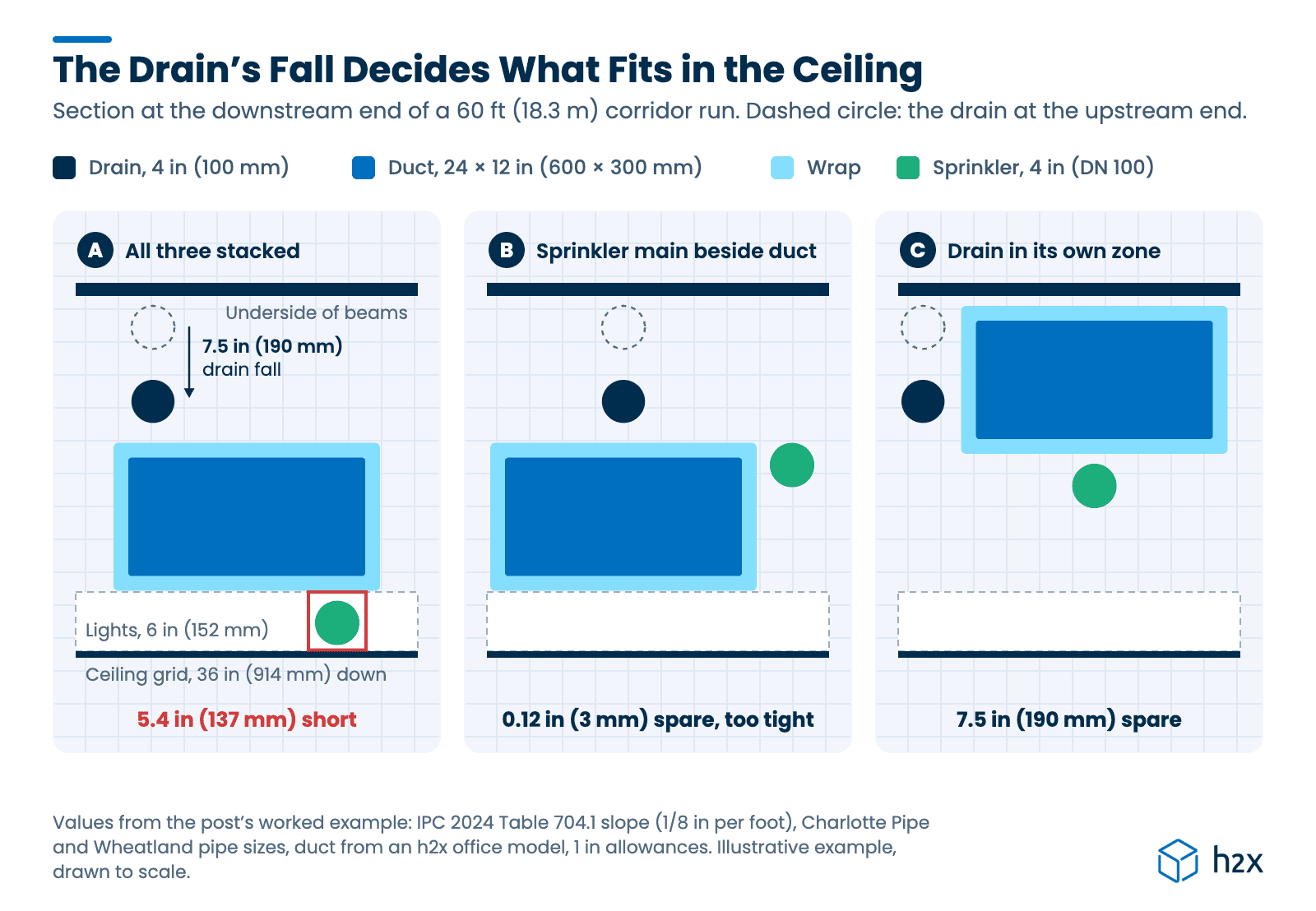
Moving the sprinkler main beside the duct technically fits, with 0.12 in (3 mm) to spare. But if the drain comes out at the top of its tolerance, 4.47 in (Charlotte Pipe), that drops to 0.03 in (1 mm). So in practice it doesn’t fit.
Choosing a Fix
Step 3, pick a fix. If the corridor is wide enough, give the drain its own zone beside the duct and sprinkler main, which stay stacked one under the other. That leaves 16.1 in (409 mm) spare in the drain’s zone and 7.5 in (190 mm) in the duct and sprinkler zone.
Alternatively, change the duct to 30 × 10 in (750 × 250 mm). Its equivalent diameter is 18.3 in (465 mm), the same as the 24 × 12 in duct’s, using ASHRAE’s equal-friction relationship (Fundamentals 2025, Chapter 21, Equation 25). That gives 2.1 in (54 mm) spare with the sprinkler main beside it.
However, the duct uses 11% more sheet metal per foot and needs a wider zone. Its fittings also need checking again, since equal friction in straight duct doesn’t make fitting losses equal.
So the drain fixes the levels, and everything else works around it. Slopes vary between codes, too. In England, Approved Document H (2015 edition) sends complex systems in larger buildings to BS EN 12056 (paragraph 1.1). For a 100 mm (4 in) drain below ground, it asks for 1:40 or 1:80, depending on peak flow (Table 6). So check the minimum slope your own code sets for the pipe you’re running before you set ceiling heights.
When MEP Coordination Problems Reach Site
Some clashes still get through to site, and the fix follows the same pattern each time. First, trace the cause to the model or drawings and raise an RFI with the trades involved. Then get the new route approved, rerun the checks it affects, and update the model and record drawings.
A Clash Found During Installation
When a fitter finds a clash, the trade raises an RFI rather than improvising a route. The designer or coordinator then proposes a reroute, and the architect or engineer approves it. Afterwards, update the model, because the record drawings have to show what was actually built.
Cable Tray and Conduit Clashes
Electrical services often go in last, so they’re the ones that find no room. To avoid that, keep a cable tray zone in the routing priority from the start. Leave the 12 in (305 mm) of access space the NEC asks for above it, too.
Low Water Pressure After a Reroute
A rerouted pipe usually gains bends and length, and each one adds pressure loss. So after any reroute, recheck the pipe sizes and the pressure at the furthest fixture. Then confirm the booster pump or the incoming supply still covers it.
Sprinkler Mains Moved During Coordination
A moved sprinkler main changes the pipe lengths and fittings in its hydraulic calculation. So rerun the calculation before the system is tested, rather than finding out when it fails.
Material Delivery Delays
Once sizes and routes are signed off, the contractor can order and prefabricate early. A late change, however, can make delivered material the wrong size, and then the trades have to resequence work around what’s arrived.
Common Mistakes
- Coordinating before the sizes are final. Size every duct and pipe first, or the clash tests check a design that’s about to change.
- Leaving the drain falls until last. Set drainage levels first, because they fix the depth every other service has to work with.
- Ignoring access and maintenance space. Run clearance tests as well as hard ones, and include valves, dampers and access panels.
- Mixing levels of development. Agree the LOD for each trade in the BIM execution plan, so one model isn’t checked against another’s placeholders.
- Treating zero clashes as done. Review insulation, supports and installation sequence too, since the clash test doesn’t see them.
How h2x Helps with MEP Coordination
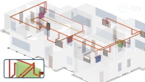
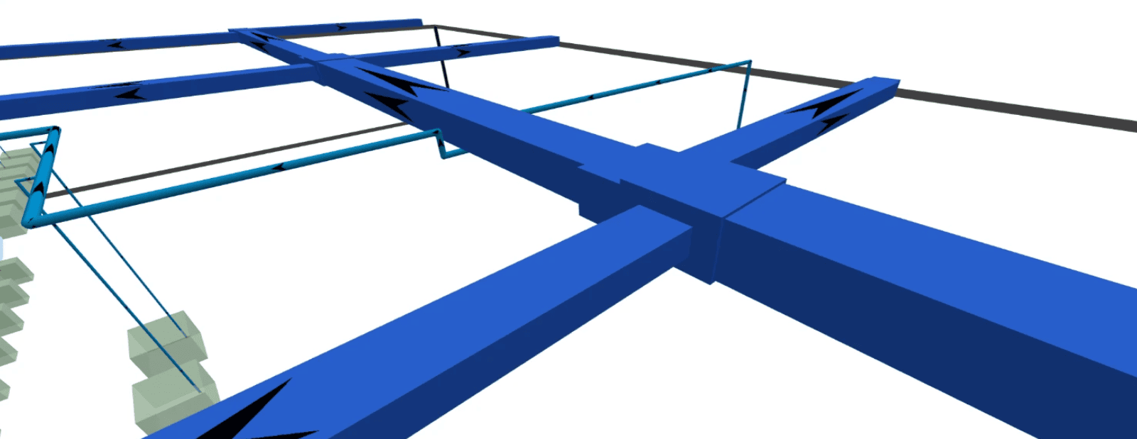
h2x design software sizes mechanical, plumbing and wet fire protection systems on your drawings, so you coordinate with real sizes rather than placeholders. In h2x’s 3D view, you see pipes, ducts and equipment with the walls, windows and doors around them. That way, you can spot clashes before you issue drawings.
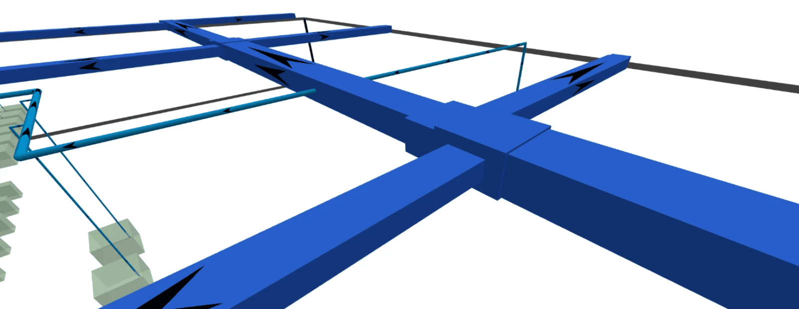
When you move a pipe or duct, h2x recalculates the system, so a reroute doesn’t leave the sizes out of date. In our office model, we dropped a 2 in (50 mm) cold water main under the duct. The furthest lavatory then fell from 42.5 to 41.9 psi (293 to 289 kPa).
From there, the Revit integration maps the sized design to your company’s Revit families. You can also export to AutoCAD.
Key Takeaways
MEP coordination works when the design is sized first, drainage sets the levels and every trade works from the same model. Clash detection finds the conflicts, but people resolve them, and the coordination drawings record the result.
- MEP coordination fits mechanical, electrical and plumbing services around the structure and each other, with room to install and maintain them.
- Common practice gives gravity drainage the space first, then large ducts, sprinkler mains, pressure pipes and cable tray.
- BIMForum’s LOD 350 is the level for construction coordination, and LOD 300 elements aren’t necessarily clash-free.
- In the worked example, a 7.5 in (190 mm) drain fall left a stack that fit 5.4 in (137 mm) short.
- After any reroute, recheck pipe sizes, pressure and sprinkler calculations.
- h2x sizes the systems before coordination, and its 3D view helps you spot clashes before export to Revit or AutoCAD.
FAQ
What does MEP coordination mean?
MEP coordination is the process of fitting a building’s mechanical, electrical and plumbing systems into the space without clashes. Each service gets a route and height that leaves room for the structure, the other trades and maintenance. The result is a set of coordination drawings that every trade signs off and installs from.
What are MEP coordination drawings?
MEP coordination drawings are combined plans and sections showing every trade’s ducts, pipes, conduit and equipment at their real sizes and heights. US specifications usually call for them in Section 01 31 00. They show bottom elevations with insulation and supports, plus access doors, maintenance space and installation sequence.
What is LOD 350?
LOD 350 is the BIMForum level of development for construction coordination. Besides its size, shape, location and orientation, an LOD 350 element shows how it meets the elements around it. That’s the detail construction coordination needs, such as clash detection and layout. Because it usually needs the trades’ craft knowledge, contractors tend to model it.
What’s the difference between clash detection and MEP coordination?
Clash detection is a software test that finds overlapping or too-close elements in a combined model. MEP coordination is the whole process around it, from sizing and routing priority to meetings, fixes and signed-off drawings. A model can pass every clash test and still lack space for hangers or access, so people still review it.
What happens when a clash is found on site?
The installing trade raises an RFI instead of improvising a route. Next, the designer or coordinator proposes a reroute, and the engineer or architect approves it. Then the team rechecks what the change affects, such as pipe sizes or sprinkler calculations, and updates the model so the record drawings match.
Does h2x do clash detection?
h2x’s 3D view lets you spot clashes between pipes, ducts, equipment and the building before you export the design. It doesn’t run automated cross-trade clash tests. For those, export the sized design to Revit or AutoCAD and run the checks in the combined model.
Check Your Design in 3D Before Coordination
h2x sizes your mechanical, plumbing and fire systems on your plans and shows them in 3D with the building around them. Spot clashes early, then export the sized design to Revit or AutoCAD for coordination.
Meet the author

Daniel Mousdell
Daniel Mousdell is the Founding Marketer at h2x, where he creates technical content and resources for HVAC and MEP engineers. Outside of work, he runs LilWayneHQ.
Article published: November 9, 2026
Last updated: November 9, 2026
Technically reviewed by: Michael Ainscough, Technical Engineer at h2x