How to Calculate Duct Size for HVAC Systems
Learn how to calculate duct size from airflow, velocity and friction rate, with a worked example for round and rectangular ducts in US and metric units.
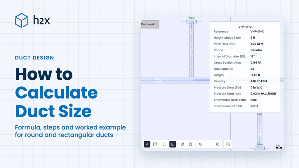
To calculate duct size, divide the airflow by a target velocity to get the duct’s cross-sectional area. Then turn that area into a diameter or a width and height. Round up to a standard size, and check the friction loss.
When you calculate duct size, both checks matter, because a duct can pass one and fail the other. Velocity sets the noise, and friction sets how much of the fan’s pressure the duct uses up. This guide covers the formula, the steps and a worked example for a main and a branch. Then it lists standard duct sizes.
Quick Answer: To calculate duct size, divide the airflow by the design velocity to get the area (A = Q / V), then find the diameter (D = √(4A / π)) or a width and height. Round up to a standard size and check its friction loss against your friction rate.
What Do You Need Before You Calculate Duct Size?
You need four inputs before you calculate duct size:
| Input | Where it comes from | Example |
|---|---|---|
| Airflow, CFM (L/s) | The heating, cooling or ventilation load for the rooms the duct serves | 1,600 CFM (755 L/s) for a main |
| Maximum velocity, fpm (m/s) | Noise limits for where the duct runs | 1,200 fpm (6.1 m/s) for a main |
| Friction rate, in. w.c. per 100 ft (Pa/m) | The fan’s available static pressure spread over the longest run | 0.12 in. w.c. per 100 ft (0.98 Pa/m) |
| Shape and material | The project spec and the space available | Round galvanized steel |
The airflow for each duct section is the sum of the airflows of everything downstream of it. A main feeding four branches of 400 CFM (189 L/s) carries 1,600 CFM (755 L/s).
The friction rate comes from the fan. For homes, ACCA Manual D divides the available static pressure by the total effective length of the longest run. Our duct sizing chart works through that formula with typical rates.
Duct Size Calculation Formula
The duct size calculation formula starts from the continuity equation. The area a duct needs is the airflow divided by the velocity you’ll allow:
A = Q / V
Here A is the area in ft² (m²), Q the airflow in CFM (m³/s) and V the velocity in fpm (m/s). In US units, keep CFM and fpm together so the area comes out in ft². The air velocity post covers this step in more detail: how to calculate air velocity in a duct.
For a round duct, the diameter follows from the area:
D = √(4A / π)
For a rectangular duct, pick one side to suit the space and divide the area by it to get the other. The velocity check always uses the duct’s real area, width × height.
The friction check uses the Darcy-Weisbach equation, with a friction factor that depends on the Reynolds number and the duct wall’s roughness. To find it, see our post on the Darcy friction factor. In practice, most engineers read the friction rate from a chart, a ductulator or software.
How to Calculate Duct Size Step by Step
- Total the CFM (L/s) flowing through the section.
- Divide it by the maximum velocity to get the area, A = Q / V.
- Convert the area to a diameter, D = √(4A / π), or to a width and height.
- Round up to the next standard duct size.
- Check the friction rate at your airflow in that size. If it’s above your design rate, step up a size and check again.
- Check the velocity in the size you’ve chosen. It can only have dropped, since the duct got bigger.
- For a rectangular duct, find a width and height whose equivalent diameter passes the friction check, with the velocity worked out on its own area.
Worked Example of a Duct Size Calculation
Take an illustrative commercial supply run. A main carries 1,600 CFM (755 L/s) to four branches of 400 CFM (189 L/s) each.
For this example, the main’s limits are 1,200 fpm (6.1 m/s) and 0.12 in. w.c. per 100 ft (0.98 Pa/m). Each branch’s limits are 800 fpm (4.1 m/s) and 0.07 in. w.c. per 100 ft (0.57 Pa/m). The ducts are galvanized steel carrying standard air.
These are example design limits, not universal recommendations. On a real project, confirm yours against the room’s noise criteria and the fan’s available static pressure.
How to Calculate Duct Size for the Main
The area is A = 1,600 / 1,200 = 1.333 ft² (0.124 m²). So the diameter is D = √(4 × 1.333 / π) = 15.6 in (397 mm).
The next standard size up is 16 in (406 mm). At 1,600 CFM (755 L/s) it runs at 1,146 fpm (5.82 m/s). Its friction loss is 0.108 in. w.c. per 100 ft (0.88 Pa/m). Both are inside the limits, so the main is 16 in (406 mm).
How to Calculate Duct Size for the Branch
The area is A = 400 / 800 = 0.500 ft² (0.046 m²), which gives D = 9.57 in (243 mm). So the first size to try is 10 in (254 mm).
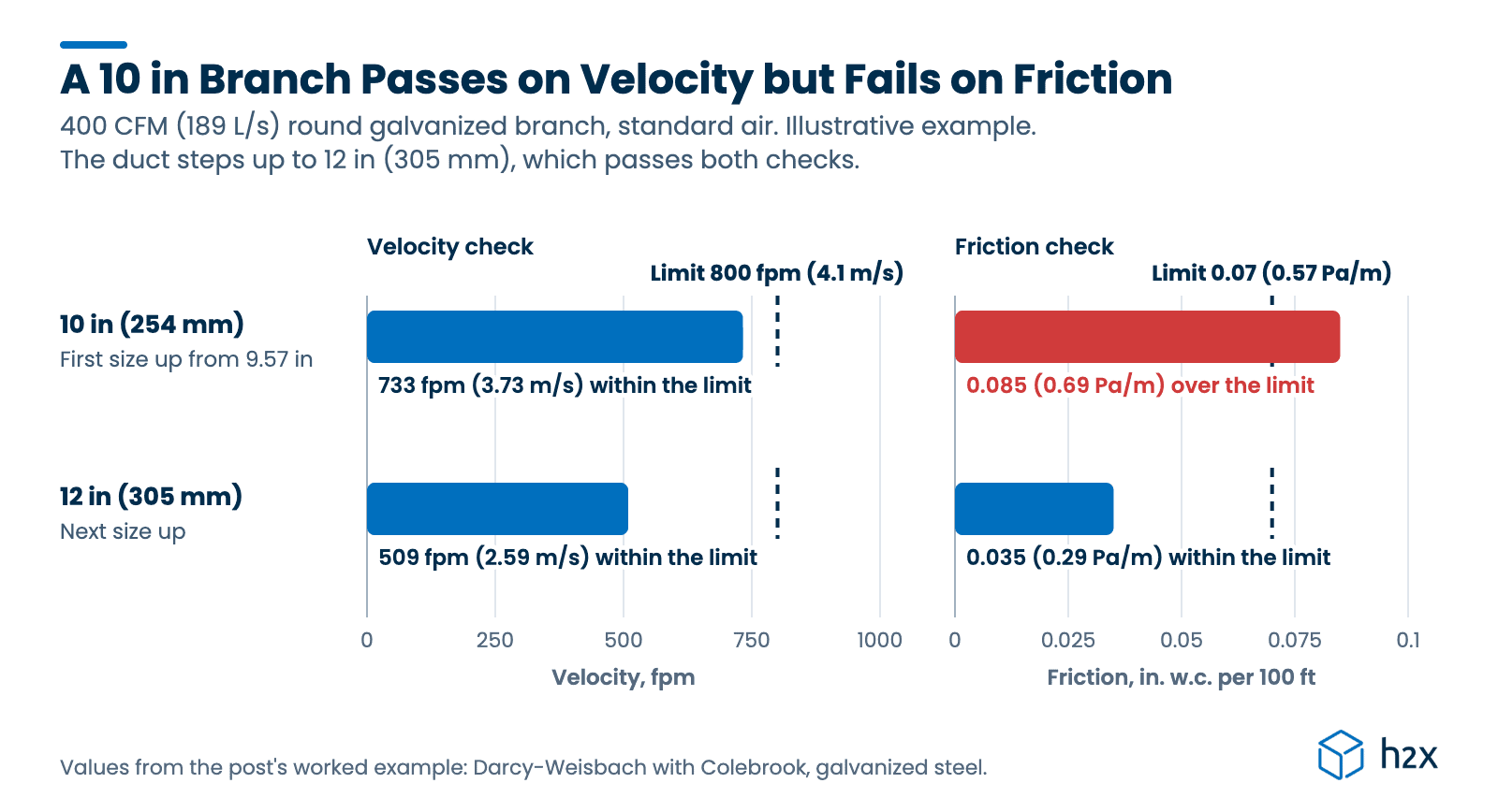
At 400 CFM (189 L/s) a 10 in (254 mm) duct runs at 733 fpm (3.73 m/s), inside the velocity limit. But it loses 0.085 in. w.c. per 100 ft (0.69 Pa/m), above the 0.07 design rate. So the velocity check passes and the friction check fails, and the branch steps up to 12 in (305 mm). There it runs at 509 fpm (2.59 m/s), losing just 0.035 in. w.c. per 100 ft (0.29 Pa/m).
This is why both checks matter. The velocity method alone would have picked 10 in (254 mm). That branch would have used more fan pressure than the design allows.
| Duct | Airflow, CFM (L/s) | Calculated size, in (mm) | Size chosen, in (mm) | Velocity, fpm (m/s) | Friction, in. w.c./100 ft (Pa/m) |
|---|---|---|---|---|---|
| Main, round | 1,600 (755) | 15.6 (397) | 16 (406) | 1,146 (5.82) | 0.108 (0.88) |
| Branch, round | 400 (189) | 9.57 (243) | 12 (305) | 509 (2.59) | 0.035 (0.29) |
| Main, rectangular | 1,600 (755) | 20 × 10 (508 × 254) fails friction | 22 × 10 (559 × 254) | 1,047 (5.32) | 0.111 (0.91) |
| Branch, rectangular | 400 (189) | 14 × 6 (356 × 152) fails friction | 12 × 8 (305 × 203) | 600 (3.05) | 0.062 (0.51) |
The rectangular rows use the same limits, with friction from each size’s equivalent diameter. A 20 × 10 in (508 × 254 mm) main has the area for 1,600 CFM (755 L/s) at 1,152 fpm (5.85 m/s). But it loses 0.138 in. w.c. per 100 ft (1.13 Pa/m), so the main goes up to 22 × 10 in (559 × 254 mm).
Which Method Should You Use to Calculate Duct Size?
The worked example sizes each duct by velocity, then checks its friction against a limit. For a whole system, Chapter 21 of the 2025 ASHRAE Handbook, Fundamentals describes two methods. Equal friction sizes the first section from the fan at a target velocity, then every section after it at one design friction rate. Static regain is the other.
| Method | What it fixes | Best for |
|---|---|---|
| Velocity method | Maximum velocity in each section | Quick sizing, short runs, noise-critical spaces |
| Equal friction | The same friction rate in every section | Most low-pressure supply, return and exhaust systems |
| Static regain | The static pressure at each branch, using the pressure recovered as velocity falls | Long, high-velocity mains with many takeoffs |
Static regain sizes each main section after a takeoff so the pressure regained from the slower air roughly offsets that section’s loss. That gives more even pressure at the branches, at the cost of an iterative calculation.
Standard Duct Sizes
When you calculate duct size, the result is never the final answer, because ducts come in standard sizes. You round up to the next one, then run the friction check on that size.
The tables below are the sizes that Recommended Sizes Only mode in h2x engineering software rounds up to. They’re metric series, with rounded inch equivalents listed first, so they aren’t necessarily standard US sizes. The worked example uses US whole-inch sizes instead, since US shops often stock round duct in whole inches. Check your fabricator’s list for the sizes you can buy.
To size a duct from a table instead of a formula, download the free ductulator chart (PDF), which covers round and rectangular ducts.
Standard Round Duct Sizes
| Diameter, in (mm) | Diameter, in (mm) | Diameter, in (mm) |
|---|---|---|
| 2.5 (63) | 7.9 (200) | 24.8 (630) |
| 3.0 (75) | 9.8 (250) | 28.0 (710) |
| 3.1 (80) | 12.4 (315) | 31.5 (800) |
| 3.5 (90) | 14.0 (355) | 35.4 (900) |
| 3.9 (100) | 15.7 (400) | 39.4 (1,000) |
| 4.9 (125) | 17.7 (450) | 44.1 (1,120) |
| 6.3 (160) | 19.7 (500) | 49.2 (1,250) |
| 22.0 (560) |
Standard Rectangular Duct Sizes
Each side of a rectangular duct comes from the same series, so any width can pair with any height:
| Side, in (mm) | Side, in (mm) | Side, in (mm) |
|---|---|---|
| 3.9 (100) | 15.7 (400) | 47.2 (1,200) |
| 5.9 (150) | 19.7 (500) | 55.1 (1,400) |
| 7.9 (200) | 23.6 (600) | 63.0 (1,600) |
| 9.8 (250) | 31.5 (800) | 70.9 (1,800) |
| 11.8 (300) | 39.4 (1,000) | 78.7 (2,000) |
How Do You Calculate Duct Size for a Rectangular Duct?
Size a rectangular duct by its equivalent diameter: the round duct that has the same friction loss at the same airflow. Huebscher’s equation gives it, and the ASHRAE duct design chapter uses it:
De = 1.30 × (a × b)^0.625 / (a + b)^0.25
Here De is the round size with the same friction, while a and b are the width and height, in one consistent unit. A rectangular duct needs more area than the round duct it replaces. In the worked example, the 22 × 10 in (559 × 254 mm) main has 220 in² (1,419 cm²) of area. The 16 in (406 mm) round duct it replaces has 201 in² (1,297 cm²).
Keep the shape close to square where the space allows. A flatter duct has more wall for the same area, so it loses more pressure and needs more sheet metal. Many designers aim for a width-to-height ratio of about 2:1. To see how that sheet metal gets priced, our guide to HVAC estimating software turns a duct takeoff into pounds by gauge.
Common Mistakes
- Stopping at the velocity check. A size can pass on velocity and fail on friction, like the worked example’s 10 in (254 mm) branch.
- Rounding down to the nearest standard size. Always round up, then check friction in the size you’ve picked.
- Sizing a rectangular duct by area alone. Use its equivalent diameter for friction; equal area isn’t equal friction.
- Using one velocity for mains and branches. Branches near occupied rooms need lower velocities than mains in a shaft.
- Forgetting that airflow changes along a main. Size each section for the airflow it carries after the last takeoff.
How h2x Helps with Duct Size Calculations
To calculate duct size for a whole system by hand, you repeat these checks for every section. And you redo them whenever an airflow changes. h2x design software runs the duct size calculation for every duct as you draw.
In Settings > Methods, the Duct Sizing Method sets the checks: Maximum velocity, Maximum pressure drop, or both. Each duct then rounds up to the next standard size under Recommended Sizes Only. Or you can switch it to a step increment or the exact size. You can override the limits, the material, the shape and the size on any single duct. Change an airflow or reroute a run, recalculate, and the duct sizes downstream follow.
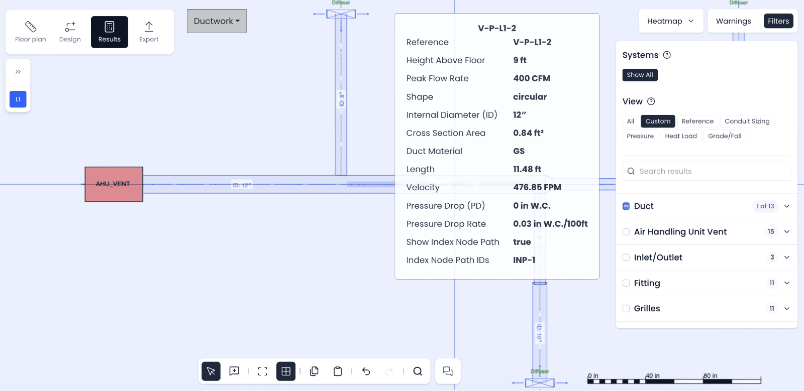
h2x sizes the 400 CFM (189 L/s) branch at its 12.4 in (315 mm) size, shown as 12″ in imperial units. So it runs at 477 fpm (2.42 m/s), a little slower than a true 12 in (305 mm) duct. It loses 0.03 in. w.c. per 100 ft (0.25 Pa/m), within the 0.07 limit.
h2x’s ventilation calculations are verified by CIBSE and are aligned with ASHRAE methods. For a quick check on one duct, try our duct size calculator or the ductulator.
You can watch the metric version of the HVAC Design in h2x video here.
Key Takeaways
To calculate duct size, you run two checks: the area the velocity limit allows, and the friction loss in the standard size you round up to. Do both for every section, starting from the airflow it carries.
- Formula: area A = Q / V, then diameter D = √(4A / π), or a width and height with the same area or more.
- Round up: pick the next standard size up, then check friction in that size.
- Worked example: a 1,600 CFM (755 L/s) main sizes to 16 in (406 mm), and a 400 CFM (189 L/s) branch to 12 in (305 mm).
- Rectangular ducts: size them by equivalent diameter, but work out velocity on the real area.
- h2x: h2x runs the velocity and pressure drop checks on every duct and rounds up to standard sizes as you draw.
FAQ
What is the formula for duct size?
The basic duct size formula is A = Q / V: the area equals the airflow divided by the velocity. In US units, CFM divided by fpm gives the area in ft². For a round duct, the diameter is then D = √(4A / π). Round up to the next standard size and check its friction loss.
How do you calculate duct size from CFM?
To calculate duct size from CFM, divide the CFM by your maximum velocity in fpm to get the area in ft². For example, 400 CFM (189 L/s) at 800 fpm (4.1 m/s) needs 0.5 ft² (0.046 m²). That’s a 9.6 in (243 mm) round duct. Round up to 10 in (254 mm), then check friction. At 0.07 in. w.c. per 100 ft (0.57 Pa/m), 10 in is too small and 12 in (305 mm) works.
What are standard duct sizes?
In the metric series h2x uses, standard round ducts run from 2.5 in (63 mm) to 49.2 in (1,250 mm). Standard rectangular sides run from 3.9 in (100 mm) to 78.7 in (2,000 mm). US shops often stock round duct in whole inches. Check your fabricator’s list.
What velocity should a duct run at?
It depends on the duct’s location and how quiet the room needs to be. For example, this guide uses about 1,200 fpm (6.1 m/s) for mains and 800 fpm (4.1 m/s) for the branches. ASHRAE’s duct design chapter lists maximum velocities for each duct location and noise rating.
Can a duct pass the velocity check but fail the friction check?
Yes. In the worked example, a 10 in (254 mm) branch carries 400 CFM (189 L/s) at 733 fpm (3.73 m/s). That’s inside an 800 fpm (4.1 m/s) limit. But it loses 0.085 in. w.c. per 100 ft (0.69 Pa/m), over the 0.07 design rate. So it steps up to 12 in (305 mm).
Can h2x calculate duct sizes for a whole system?
Yes. In Settings > Methods, you choose whether h2x sizes ducts by velocity, pressure drop or both, and it applies that to every duct. It rounds up to standard sizes unless you choose exact sizes, and you can override any duct. When an airflow changes, the sizes downstream update.
Stop Sizing Ducts by Hand
h2x calculates velocity, friction factor and pressure drop for every duct in your design, with no manual formulas or trial sizes. Each duct is sized against your limits and rounded up to a standard size.
Meet the author

Daniel Mousdell
Daniel Mousdell is the Founding Marketer at h2x, where he creates technical content and resources for HVAC and MEP engineers. Outside of work, he runs LilWayneHQ.
Article published: April 17, 2024
Last updated: November 2, 2026
Technically reviewed by: Jonathan Mousdell, Mechanical Engineer and Co-founder at h2x