Recirculation Pumps: Sizing and Selection Guide
A practical engineering guide to calculating recirculation pump flow and head, identifying the index circuit, reading pump curves and selecting the correct duty point.
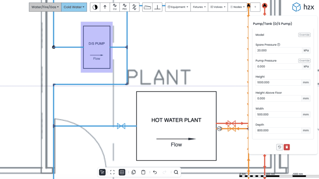
Download your free PDF of this article below.
Recirculation pumps maintain flow through hot water circulation loops, helping keep heated water available throughout the distribution system.
Correct pump selection depends on two main values: the required circulation flow rate and the pump head. Flow is primarily determined by system heat loss and the selected flow to return temperature difference. Pump head is based on pressure losses around the index circuit.
This guide explains how to calculate recirculation pump duty, understand pump curves, compare pump arrangements and coordinate the selected pump within a hot water system.
What Are Recirculation Pumps?
A recirculation pump moves water around a closed circulation loop and back towards the hot water source.
In a hot water system, this helps keep heated water closer to outlets. It can reduce waiting times and the amount of cooled water discharged before hot water arrives.
The difference between a dead leg system and a recirculating system is shown below.
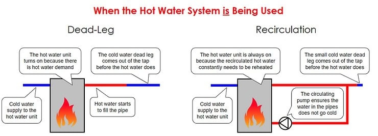
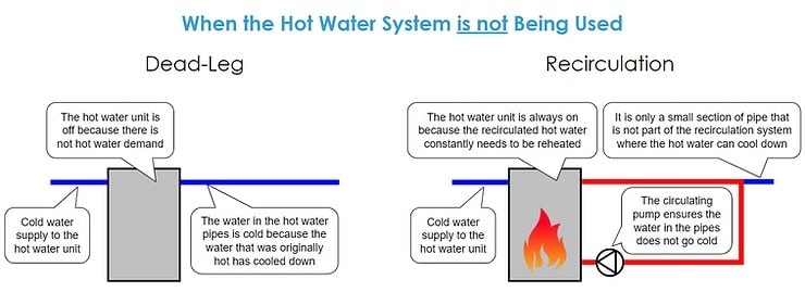
A dead leg system relies on users drawing cooled water from the pipe before hot water reaches the outlet. A recirculating system instead keeps water moving through a return loop, reducing the length of pipework that can cool between uses.
For a broader explanation of system operation, controls, installation and energy use, see our complete guide to hot water recirculating pumps.
Do You Need a Recirculation Pump?
Whether a project requires a recirculation pump depends on the building, distribution layout, pipe lengths and hot water delivery requirements.
In larger buildings, a hot water recirculation system can provide two main benefits:
- Reduced waiting time for hot water to reach outlets
- Reduced water waste while users wait for hot water
However, recirculation is not the only possible approach. Multiple local hot water sources can also reduce dead leg lengths by serving smaller areas of the building independently.
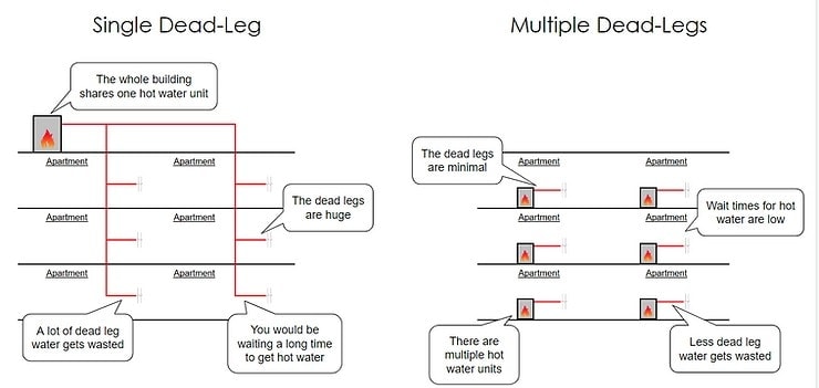
This arrangement can simplify the distribution pipework, but it requires additional hot water sources. A central hot water system with recirculation may therefore be more appropriate where reducing the number of separate hot water sources is an important design consideration.
The most suitable approach depends on the building layout, system requirements, energy use, installation requirements and project cost.
Recirculation Pump Duty
Two main values define recirculation pump duty: the required flow rate and pump head.
Recirculation Pump Flow Rate
Base the required circulation flow rate on the heat loss from the relevant hot water distribution pipework.
As hot water circulates through the system, heat is lost through the pipes and insulation. The circulation flow must be sufficient to offset this heat loss while maintaining the selected temperature difference between the flow and return.
Calculate the system heat loss in kW, then convert it into the required circulation flow rate.
Recirculation Pump Head
The pump must also provide enough head to overcome the pressure losses created by the circulation system at the calculated flow rate.
Pressure losses can occur through:
- Pipes
- Fittings
- Check valves
- Balancing valves
- Isolation valves
- Other system components
The required pump head is normally based on the index circuit.
The index circuit is the complete circulation route with the greatest pressure loss when measured from the hot water source and back again. Do not add the pressure losses from separate parallel circuits together.
An example of the index circuit is shown below:
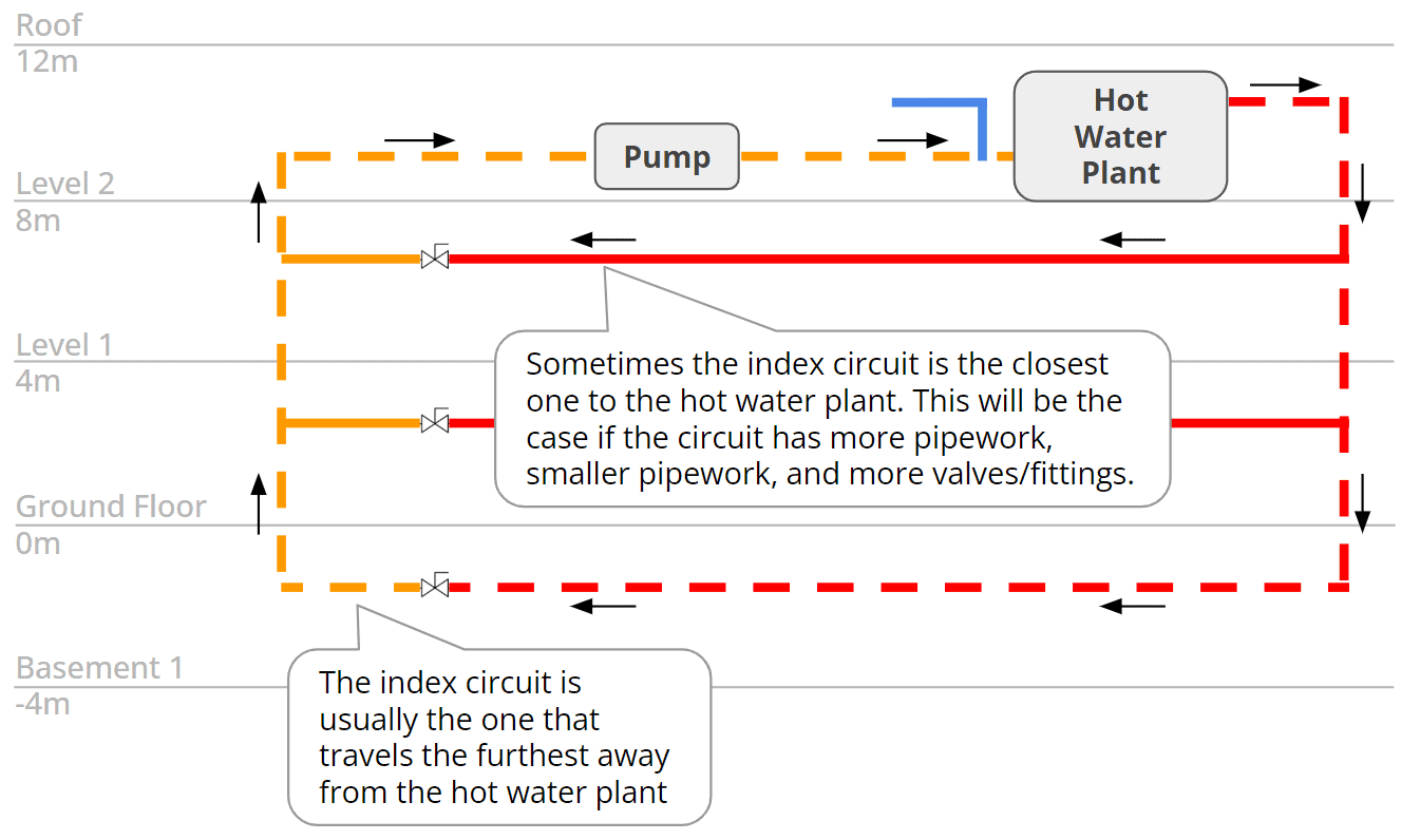
Static building height is generally not added to the required pump head in a closed recirculation loop. Water that rises through the system also descends as it completes the circuit, so the pump primarily needs to overcome friction and component pressure losses.
High-rise hot water systems still need a separate pressure strategy to account for static pressure, PRVs and pressure zoning. See our guide to hot water recirculation design for high-rise buildings.
Together, the required flow rate and pump head form the pump duty point. This duty point is then compared with the manufacturer’s pump curve when selecting a suitable recirculation pump.
How to Calculate Recirculation Pump Flow Rate
To calculate the required recirculation flow rate, first determine the heat loss from the hot water distribution system.
The following factors can affect pipework heat loss:
- Pipe length and diameter
- Water temperature
- Ambient temperature
- Insulation type and thickness
- Conditions around the pipework
Use project-specific design values rather than relying on one universal ambient temperature or air movement assumption.
Depending on the calculation method, heat loss data published by the insulation manufacturer may also be available for the selected pipe and insulation arrangement.
Once you know the system heat loss, convert it into the circulation flow required for the selected flow to return temperature difference, or ΔT.
Recirculation Pump Flow Rate Equation
The calculation is:
Mass Flow Rate = System Heat Loss ÷ (Specific Heat Capacity × ΔT)
For example, assume:
- System heat loss = 5 kW
- Flow to return ΔT = 5°C
- Specific heat capacity of water = approximately 4.185 kJ/kg·K
The calculation is:
5 kW ÷ (4.185 kJ/kg·K × 5°C) = 0.239 kg/s
Because the density of water is approximately 1 kg/L under typical system conditions, this is approximately:
0.239 L/s
or:
0.86 m³/h
A smaller permitted temperature difference generally requires a higher circulation flow rate because more water must circulate to limit the temperature reduction around the system.
Recirculation Pump Flow Rate in US Customary Units
You can express the same example in US customary units.
A heat loss of 5 kW is approximately 17,061 BTU/hr, while a 5°C temperature difference is equivalent to 9°F.
Using a specific heat capacity of approximately 1 BTU/lb·°F:
17,061 BTU/hr ÷ (1 BTU/lb·°F × 9°F) = 1,896 lb/hr
This is approximately:
3.79 US gpm
The required circulation flow in this example is therefore approximately:
0.239 L/s, equivalent to 0.86 m³/h or 3.79 US gpm
How to Calculate Recirculation Pump Head
Once the required circulation flow rate is known, calculate the pressure losses through the index circuit at that flow.
The calculation should include the relevant pressure losses from pipes, fittings, check valves, balancing valves and other components along the complete circulation route.
These losses combine to determine the required pressure differential, which can then be expressed as pump head for pump selection.
If the result is calculated as pressure, it can be converted into pump head using:
Head = Pressure Difference ÷ (Fluid Density × Gravitational Acceleration)
For water:
10 kPa ≈ 1.02 m of head
In US customary units:
1 psi ≈ 2.31 ft of head
For example, an index-circuit pressure loss of approximately 35 kPa is equivalent to approximately 3.6 m of head.
For a more detailed explanation of calculating losses through pipes, valves and fittings, see our pressure loss calculation guide.
The required flow rate and calculated pump head together form the pump duty point. This can then be plotted against a manufacturer’s pump curve to determine whether a particular recirculation pump can meet the required duty.
Recirculation Pump Curves
Once the recirculation pump duty has been calculated, the next step is to compare it with available pump performance.
A pump curve shows the relationship between the flow a pump can provide and the corresponding head.
Manufacturer pump curves typically show the relationship between flow (Q) and head (H), which allows the calculated duty point to be compared with the pump’s available performance.
The main values are:
- Q: Flow
- H: Head
The required flow and head create the duty point that should be compared with the pump curve.
Recirculation Pump Curve Example
Assume a hot water recirculation system requires:
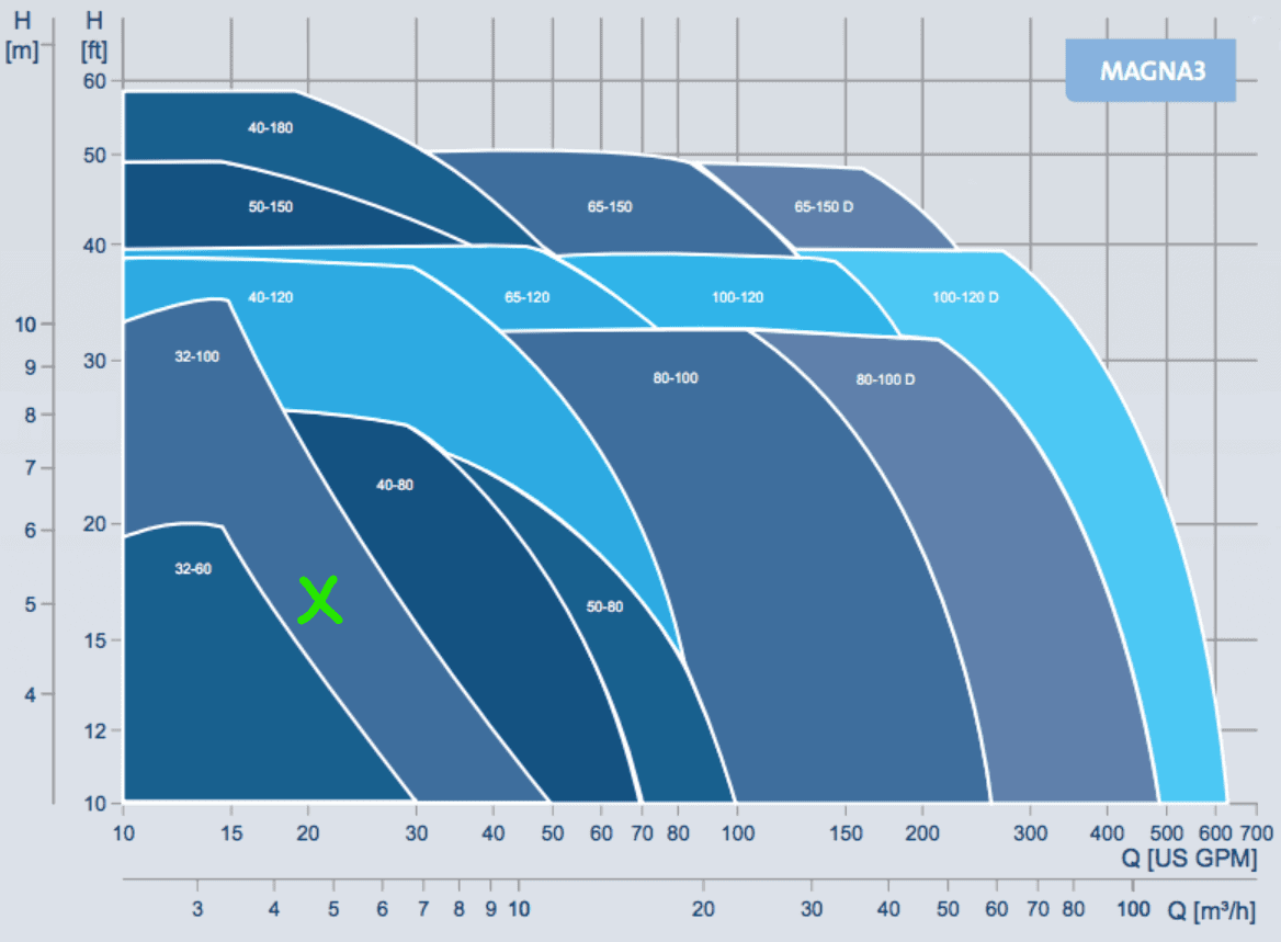
4.8 m³/h at 5 m head
This is approximately:
21 US gpm at 16.4 ft head
If this duty point falls outside the operating range of a particular pump, that pump cannot provide the required combination of flow and head.
In the example below, the required duty falls outside the available range of the 32-60 pump.
However, the duty point falls within the available range of the 32-100 pump.
The 32-100 therefore provides the required hydraulic performance in this example.
Do not base pump selection only on choosing a model with the greatest maximum flow or head. The required duty point should fall within an appropriate part of the manufacturer’s stated operating range.
Also, avoid oversizing where possible. Unnecessarily high flow can increase pipe velocity, system pressure loss and pump energy use.
What Recirculation Pump Arrangements Are Available?
A hot water recirculation system can use different pump arrangements depending on the required capacity, redundancy and acceptable downtime.
Three common terms are duty, standby and assist.
Duty Pump
The duty pump provides the required circulation flow and head during normal operation.
A single-duty arrangement can be appropriate where temporary loss of circulation during maintenance or pump failure can be accepted.
Standby Pump
A standby pump provides backup if the duty pump becomes unavailable.
The standby pump is normally selected to provide the required system duty independently.
Duty and standby pumps may also alternate during normal operation to distribute runtime between the units.
Assist Pump
An assist pump operates alongside another pump where additional capacity is required.
Unlike a standby pump, which primarily provides redundancy, an assist pump contributes to the required operating capacity.
Choosing a Recirculation Pump Arrangement
The appropriate arrangement depends on factors including:
- Required redundancy
- Building use
- Acceptable downtime
- Maintenance requirements
- System criticality
- Project design requirements
A duty/standby arrangement provides additional resilience because circulation can continue if one pump becomes unavailable.
However, not every system requires the same level of redundancy. The arrangement should be selected according to the individual project rather than applying one configuration universally.
Recirculation Pumps: Installation and Design Coordination
Selecting the hydraulic duty is only one part of specifying a recirculation pump.
The design team should also coordinate the services required for the pump to operate, remain accessible and support any required monitoring or controls.
Where Should the Recirculation Pump Be Located?
A hot water recirculation pump is typically installed on the return pipe close to the hot water source.
From this position, the pump circulates water through the distribution system and returns it for reheating.
The exact arrangement should follow the system design and pump manufacturer’s requirements.
Designers should also consider check valves, isolation valves, balancing, maintenance access and the location of controls or temperature sensors.
Electrical Requirements
The electrical design should account for the pump’s power requirements and location.
Relevant information may include:
- Electrical supply
- Pump location
- Motor requirements
- Local isolation
- Control requirements
These details should be coordinated with the electrical design team before installation.
BMS and Control Requirements
Where a building management system (BMS) is used, the design may also require pump monitoring and control points.
Depending on the project, these can include:
- Pump run status
- Pump fault status
- Duty/standby status
- Start/stop control
- Temperature monitoring
- Alarms
The required BMS points should be defined according to the project controls strategy and pump arrangement.
Temperature and Pressure Monitoring
Temperature and pressure monitoring can help designers, operators and maintenance teams understand how the circulation system is performing.
Depending on the system design, gauges or sensors may be provided at locations including:
- The incoming water supply to the hot water source
- The inlet to the recirculation pump
- Selected hot water circuits
- The outlet of the recirculation pump
- Key flow and return locations
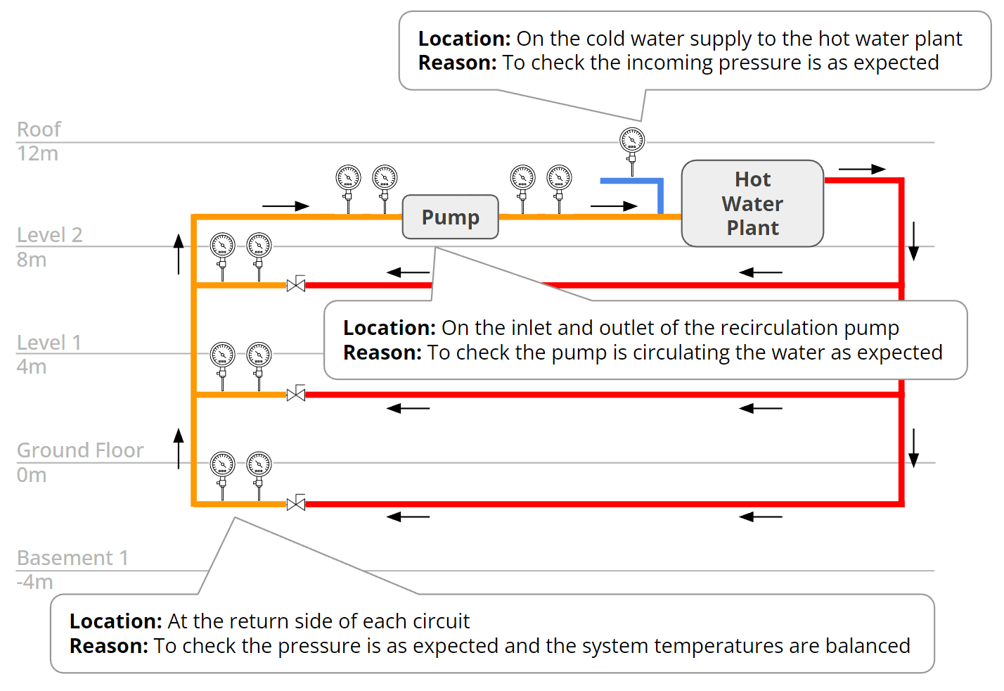
Temperature readings can help confirm whether the system is maintaining the required conditions throughout the distribution network.
Pressure readings can help identify unexpected resistance or operating conditions.
When unusual readings occur, comparing measurements at different points in the system can also make troubleshooting easier and less intrusive.
The exact monitoring arrangement should reflect the project requirements and any applicable water-management procedures.
Calculating Recirculation Pump Duty in h2x
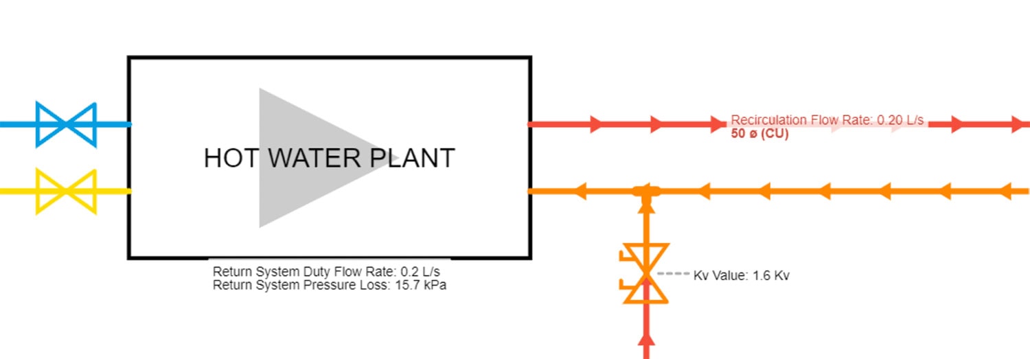
Manual recirculation pump sizing requires calculations for system heat loss, circulation flow, pipe sizing, pressure loss and balancing.
h2x performs these calculations directly from the system layout and project design parameters.
Simply sketch the hot water distribution system, define the project settings and add the required system components.
h2x can then calculate results including:
- Return system duty flow
- Return system pressure loss
- Pipe return flow
- Return system heat loss
- Balancing valve Kv
- Pipe diameter
- Pipe velocity
- Dead leg results
This connects the system layout and engineering calculations within one workflow.
For a step-by-step look at creating the complete system, see our hot water recirculation system design workflow in h2x.
The resulting recirculation pump duty can then be used when reviewing manufacturer pump curves and selecting equipment for the project.
Calculate pump duties faster in h2x
Build your hot water system layout while calculating flow rates, sizing pipes and determining pump duties in one connected workflow.
Recirculation Pump FAQs
What Is Recirculation Pump Duty?
Recirculation pump duty is the combination of flow and head that the pump must provide. The flow is primarily based on system heat loss and the selected flow to return temperature difference, while the head is based on pressure losses through the index circuit.
How Do You Size Recirculation Pumps?
Recirculation pumps are sized by calculating the required circulation flow rate and pump head. These values form the duty point, which is then compared with the manufacturer’s pump curve to select a suitable pump.
How Is Recirculation Pump Flow Rate Calculated?
Recirculation flow is calculated from the heat loss of the distribution system, the specific heat capacity of water and the selected flow to return temperature difference. Greater heat loss or a smaller permitted ΔT generally requires a higher circulation flow rate.
What Is the Index Circuit in a Recirculation System?
The index circuit is the complete circulation route with the greatest pressure loss when measured from the hot water source and back again. It normally determines the required recirculation pump head.
How Do You Calculate Recirculation Pump Head?
Calculate the pressure losses through the pipes, fittings, valves and other components around the index circuit at the required flow rate. The resulting pressure differential can then be converted into the pump head required at the duty point.
How Do You Read a Recirculation Pump Curve?
Find the required flow on the horizontal axis and the required head on the vertical axis. Their intersection forms the duty point. The selected pump must be capable of operating at that combination of flow and head within its permitted operating range.
What Is a Duty/Standby Recirculation Pump Arrangement?
A duty/standby arrangement uses one pump for normal circulation and another as backup. This provides redundancy if the duty pump becomes unavailable. Whether this arrangement is required depends on the building, acceptable downtime and project requirements.
Meet the author

Jonathan Mousdell
Jonathan Mousdell is a Mechanical Engineer and co-founder of h2x, where he creates technical content and resources for MEP engineers.
Article published: December 13, 2022
Last updated: August 27, 2026