Hydronic Snow Melt Systems: How to Size & Design Them Correctly
A complete technical guide to hydronic snow melt design for HVAC engineers: what to calculate, what to avoid, and how to get it right before the slab is poured.

Sizing hydronic snow melt systems means calculating the heat output, tube layout, flow rates, and heat source capacity needed to reliably melt snow from a surface. Get the sizing right, and you have a system that performs quietly for decades. However, get it wrong, and you have an expensive slab that can’t keep up on the one day it needs to.
Key Takeaways:
- Heat flux is the starting point for all other sizing decisions.
- ASHRAE classifies snow melt systems by performance requirement, from residential (Class I) to critical-access (Class III).
- Tube spacing and supply temperature must be designed together, not in isolation.
- Under-slab insulation is not optional — it directly determines system efficiency.
- Boiler selection must account for load, glycol viscosity, and condensing mode limitations.
What Is Hydronic Snow Melt System Sizing?
Sizing hydronic snow melt systems is the process of calculating the correct heat output, pipe layout, flow rates, and heat source capacity for a system that circulates heated fluid — typically a water and propylene glycol mix — through tubing embedded in a slab or paved surface.
The goal is to deliver enough heat at the surface to melt snow and ice at the required rate, without over-designing the system and wasting energy or budget.
Unlike radiant floor heating, snow melt systems work against outdoor conditions, including sub-zero air temperatures, wind exposure, and varying snowfall rates. That makes accurate sizing critical.

h2x design software generates both a 2D circuit layout and a 3D model view simultaneously, giving engineers a complete picture of the hydronic snow melt design before anyone installs a single pipe.
Why Getting the Sizing Right Matters
An undersized system fails at the worst possible time. If the heat flux is too low for local climate conditions, the slab cannot keep up during a heavy storm. The result is an expensive installation that requires manual clearing.
On the other hand, an oversized snow melt system wastes capital. Over-specified boilers, unnecessarily tight tube spacing, and over-built manifolds add cost without improving performance.
Poor sizing also creates operational problems:
- Unbalanced circuits cause uneven surface temperatures.
- Meanwhile, incorrect flow rates lead to poor heat transfer and short-cycling boilers.
- As a result, skipped insulation causes significant downward heat loss, inflating running costs for the life of the system.
Getting the sizing right at the design stage is far cheaper than correcting it after the slab is poured.
How to Size Hydronic Snow Melt Systems: Step-by-Step Design Process
- Determine the required heat flux. Using ASHRAE 51.06 as your framework, your design output in BTU/hr·ft² (or W/ft²) depends on local snowfall rate (liquid equivalent), ambient design temperature (99% heating design condition), and wind exposure. For most Class I residential systems in cold climates, target 150–200 BTU/hr·ft². Class II commercial systems typically require 200–250 BTU/hr·ft².
- Select your ASHRAE performance class. First, Class I is standard for residential driveways and walkways. Next, Class II applies to commercial entrances and high-traffic pedestrian areas. Finally, Class III is for critical-access locations such as hospitals and fire stations — if you are designing Class III, engage a specialist engineer.
- Choose tube size and spacing. Most hydronic snow melt circuits use ½” or ¾” PEX-A — PEX-A is preferred over PEX-B due to its superior resistance to freeze-thaw cycling and pressure transients. Standard spacing is 6″, 9″, or 12″ on center, depending on the required output and available supply temperature.
- Set supply temperature and delta-T. Target a supply temperature of 120°F–140°F with a ΔT of 20–30°F across the circuit. Tighter tube spacing allows lower supply temperatures and more even surface heat distribution. Wider spacing with higher supply temperatures introduces hot and cold spots and accelerates glycol degradation over time.
- Afterwards, size and balance your circuits. Keep individual circuits under 300 linear feet for ½” PEX and under 400–450 feet for ¾” PEX to maintain manageable pressure drops. Run all circuits home to a stainless or brass manifold and balance them to within 10–15% of each other in length. Wildly unbalanced circuits cannot be fully corrected with balancing valves alone.
- Size the heat source. Calculate the full connected snow melt load and size your boiler accordingly. If the system shares a boiler with space heating, apply appropriate simultaneous load assumptions and priority logic. Add a buffer tank if the boiler’s minimum firing rate creates short-cycling risk against a low-mass slab.
- Finally, specify your controls. A pavement-mounted sensor wired to a dedicated snow melt control module monitors both surface temperature and moisture simultaneously. This ensures the system runs only when needed. Enable slab preheat logic in climates prone to rapid storm onset; bringing the slab to approximately 35°F before precipitation hits significantly reduces the energy demand spike at storm start.
Common Snow Melt Design & Sizing Mistakes to Avoid
- Skipping under-slab insulation. Without a rigid foam insulation layer (minimum R-10) beneath the slab, a significant portion of heat migrates downward into the ground rather than upward to the surface. This is one of the most common and costly mistakes in snow melt installation.
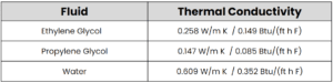
- Ignoring glycol viscosity in pump sizing. A 30–35% propylene glycol solution has higher viscosity than water. Pump curves shift left. If you size your circulator from water-based flow charts without correction, you will under-deliver flow at design conditions.
- Assuming a condensing boiler runs at rated efficiency. Snow melt return temperatures typically come back too warm (often 100–115°F) for a condensing boiler to stay in condensing mode. Do not use the 95–96% AFUE figure in your energy calculations. Model realistic efficiency based on actual return temperatures.
- Over-relying on rules of thumb for tube spacing. Defaulting to a single spacing without matching it to your actual supply temperature and required heat flux is a common shortcut that leads to underperforming systems.
- Designing unbalanced circuits. Circuits that vary significantly in length create flow distribution problems that no amount of balancing valve adjustment will fully correct. Therefore, be sure to balance at the design stage, not after.
Hydronic Snow Melt System Design in Practice: A Worked Example
Consider a 550 ft² residential driveway in Minneapolis, Minnesota. Using this location, the design conditions (ASHRAE 99% heating) call for an outdoor temperature of -16°F and moderate wind exposure. As a result, the required heat flux works out to approximately 125 BTU/hr·ft², placing it firmly in the upper range of Class I residential.
The designer specifies ½” PEX-A at 6″ spacing, with a supply temperature of 130°F and a 25°F ΔT. The driveway is divided into three balanced circuits of approximately 245 feet each, all homing to a central stainless manifold.
Total connected snow melt load: approximately 79,000 BTU/hr. The designer selects a dedicated condensing boiler rated at 100,000 BTU/hr input, with a separate buffer tank to prevent short-cycling during partial-load conditions. A pavement-mounted sensor with slab preheat logic is included in the control spec.
The designer installs R-10 rigid foam insulation beneath the full slab. The estimated running cost reduction compared to an uninsulated design is approximately 18–22% annually, based on modeled downward heat loss.
Best Practices for Hydronic Snow Melt Sizing and Installation
- Calculate heat flux from actual climate data, not generic rules of thumb. Use ASHRAE design conditions specific to the project location.
- Always specify PEX-A over PEX-B for snow melt applications. The performance difference in freeze-thaw cycling conditions is significant.
- Match tube spacing to supply temperature. Design these two variables together, not independently.
- Install R-10 or better rigid foam insulation under every snow melt slab, without exception.
- Account for glycol viscosity when selecting circulators. Use corrected pump curves for your specific glycol concentration.
- Size boilers for realistic return temperatures, not rated condensing efficiency.
- Include a pavement sensor and dedicated control module to prevent the system running on cold-but-dry days.
- Balance circuits at the design stage. Do not rely on field balancing to compensate for poor circuit layout.
How h2x Helps Engineers Design Hydronic Snow Melt Systems

h2x calculates loop spacing, heat output, and circuit lengths automatically — updating in real time as you draw.
h2x design software automates the calculations covered in this guide. Draw your slab areas, and the software calculates heat loss, sizes your loops, and splits circuits automatically to stay within maximum loop length.
From there, you can generate a full PDF design report, bill of materials, and AutoCAD or Revit export — all from the same model.
Watch a recorded h2x demo below to see how the software handles radiant and snow melt load calculations, or book a 1:1 discovery call to see it applied to your own projects.
Final Thoughts
Getting hydronic snow melt systems sized correctly requires working through heat flux, tube spacing, supply temperatures, circuit balance, and heat source capacity as a connected design process — not a checklist of independent decisions. Every variable affects the others.
The time to get the sizing right is before the concrete is poured. As a result, well-designed hydronic snow melt systems will perform reliably for 30+ years. A poorly sized one will underperform from day one and cost significantly more to operate.
FAQs About Hydronic Snow Melt Sizing
What is heat flux in a hydronic snow melt system?
Heat flux is the rate of heat output per unit area of the slab, expressed in BTU/hr·ft² or W/ft². In fact, it is the primary design parameter for a snow melt system and is determined by local climate conditions, snowfall rate, and the ASHRAE performance class required for the application.
What is the difference between ASHRAE Class I, II, and III snow melt systems?
ASHRAE classifies snow melt systems by the performance level required. Class I is standard for residential applications — the system melts snow at a reasonable rate after snowfall. Next, Class II is required for commercial areas where the surface must stay clear during active snowfall. Finally, Class III applies to critical-access locations like hospitals where zero snow accumulation is acceptable.
Why is PEX-A preferred over PEX-B for snow melt systems?
PEX-A has a higher degree of cross-linking, which gives it better flexibility at low temperatures, superior resistance to freeze-thaw cycling, and improved recovery from kinks. These properties matter significantly in snow melt applications where the tubing is subject to repeated thermal cycling over its lifetime.
How does glycol affect circulator sizing?
Propylene glycol increases the viscosity of the fluid compared to water. This shifts the pump curve to the left, reducing flow at a given head. If you size a circulator using water-based data without applying a viscosity correction factor for your glycol concentration, you will deliver less flow than the system requires at design conditions.
Do I need a dedicated boiler for a hydronic snow melt system?
Not always, but the snow melt load must be properly accounted for in the heat source capacity. If an existing boiler is used, it must have sufficient remaining capacity to handle the snow melt load simultaneously with any other connected loads. Because of this, add a dedicated buffer tank to prevent short-cycling.
Ready to streamline your hydronic snow melt design?
Stop sizing snow melt systems by hand. See how h2x automates loop layouts, manifold sizing, and design reports in one workflow.
Meet the author

Andrew Spencer
Andrew Spencer is a Mechanical Engineer at h2x.
Article published: May 19, 2026
Last updated: May 27, 2026