How to Size Water Pipes
To size water pipes correctly is critical for the performance of your design. Below, we will explore the issues caused by incorrectly sized pipes, explain what to consider when sizing pipes, and work through an example pipe sizing project.

Download your free PDF of this article below.
Size Water Pipes Introduction
To size water pipes correctly is critical for the performance of your design. In this blog, we will:
- Explore the issues caused by incorrectly sized pipes;
- Explain what to consider when sizing pipes; and
- Work through an example pipe sizing project.
What if a Pipe is too Small?
If the pipe is too small, the velocity will be too high.
High velocity means:
- The pipe sizes may be non-compliant;
- The pipe’s design life is reduced and may be operating outside of the manufacturer’s warranty;
- Water flowing through the pipe will create noise that could be a nuisance to the building occupants; and
- There could be a significant amount of pressure drop through the system - this results in the pressure at the outlets being low or means that a large pump will be required
What if a Pipe is too Big?
If the pipe is too big, the velocity will be very low.
Aside from the excessive materials and their associated cost, the main issue is that a self-cleansing velocity is not reached within the pipe.
Meeting the self-cleansing velocity prevents microorganisms from building up in the pipes and therefore helps to stop the growth of biofilm.
Without it, the system’s water quality is significantly reduced. This can be a major risk in some buildings, especially in healthcare and aged care.

What Parameters should I Design to?
There are three parameters to consider when sizing a pipe:
- The maximum velocity;
- The minimum velocity; and
- The pressure drop per metre (foot).
We describe why and when each parameter should be used:
Maximum Velocity
The maximum velocity prevents water from moving too fast through the pipes and causing the issues described above.
The maximum limit depends on some variables:
- Building location
The local standard will specify a maximum velocity which differs between countries
e.g. pipes are generally designed for higher velocities in the USA compared to the UK
- Pipe location
If the pipe is above a room such as a bedroom, the pipe velocity should be considered to avoid unwanted noise
Whereas, a pipe in a factory or below ground could be designed to a higher velocity as noise is less of a consideration
- Pipe material
Different materials are suited to different velocities
e.g. stainless steel pipes can handle higher velocities than copper pipes
- Fluid type
Pipes within the hot water systems should be designed to a lower maximum velocity than cold water pipes due to the risk of erosion-corrosion increasing at higher water temperatures
Typical maximum water velocity limits are:
Cold water - 1.5-2.4m/s (5-8ft/s)
Hot water flow - 1.2m/s (4ft/s)
Hot water return - 1m/s (3ft/s)
Minimum Velocity
There is no definitive answer to this but the general consensus is that pipe velocities should be kept above 0.6m/s (2 ft/s) to maintain the self-cleansing velocity.
Maximum Pressure Drop
You want to avoid adding pumps to your project where possible. This is because:
- They require space in the building - this is often valuable space the architect would prefer to not use as a plant room
- They increase the capital cost of the system install
- They require energy to run which:
- Increases the carbon footprint of the design
- Increases the operational costs of your design
- They require ongoing maintenance and will need to be replaced eventually
If you solely design to the velocity parameters, this can lead you to have a high amount of pressure loss through the system. Consequently, this could mean you need a pump.
So another parameter to design is to work out how much pressure you can lose through your pipes and then size the pipes based on not exceeding that.
How Should you Size Water Pipes on your Project?
It can literally be impossible to design to all three of the parameters as they contradict each other in some scenarios.
For example:
- To meet the maximum pressure drop, you might go below the minimum velocity
- To meet the minimum velocity, you might need to exceed the maximum velocity
- To meet the maximum velocity, you might not meet the minimum velocity
In these scenarios, it is up to you as an engineer to choose what works best for each project.
Whilst it is compulsory for your project to be compliant with relevant Standards, it is also very important that the design is fit for purpose.
To help you to make a decision, consider these things:
- Is poor water quality a risk to the building occupants? If so, design to the minimum velocity or at least provide filters and/or provisions for flushing the system.
- Avoiding a pump? If so, design to a maximum pressure drop and do a risk assessment on not meeting the self-cleansing velocity.
- Is noise an important consideration? If so, design to a maximum velocity and explain to your client why the pump is necessary.
If you need to make a big decision on what parameter to use, it is important to talk to your manager and project team to assess the options and determine the best way to proceed.
Example Project
Let's work through a simple project’s pipe sizing process.
Our design process will be:
- Design to the maximum velocity limit
- Check if we have sufficient pressure at the fixtures
- Check if we meet the minimum velocity limit
Building Information
The information relating to the design that we will use for the calculations is:
- The water main pressure: 240kPa (35psi)
- The water main connection: 1m (3.3ft) below ground
- The flow rate (using BS 806) is:
- Pipe supplying the WC: 0.1L/s (1.6gpm)
- Pipe supplying the Basin: 0.1L/s (1.6gpm)
- Pipe supplying the WC and Basin: 0.2L/s (3.2gpm)
- The maximum velocity limit: 1.5m/s (5ft/s)
- The minimum pressure at the fixture: 100kPa (14.5psi)
- The fixture height above ground: 1m (3.3ft)
- Valve and fitting pressure loss: 125kPa (18psi)
Pipe Layout
When drawing the pipe layout, the most important thing is to take the most direct route possible - use the least amount of bends and pipe length to get from the water main to the fixtures.
Pipe Sizing (Based on Maximum Velocity)
To find out the velocity, you will need to undertake the following calculation:
Velocity (m/s) = (Flow Rate (L/s) / 1000) / ((3.14 * (Internal Pipe Diameter (mm)/2) ^2) / 100000
Check Out Our Pipe Velocity Calculator Here
The velocity results and corresponding pipe sizes for the three pipe segments are shown in the table below:

Each of the pipes is above 0.6m/s (2ft/s) which means they meet the self-cleansing velocity.
Check the Fixture Pressure
To determine the pressure at the fixture, we need to know the following:
- Pressure at the water main connection
- The height difference between the main connection and the fixture
- Pressure loss through the valves and fittings
- Pressure drop through the pipes
The pressure results at each component in the design are shown in the table below:

The pressure at the fixture is 95.74kPa (13.9psi), which is 4.26kPa (0.6psi) below the required minimum pressure (100kPa / 14.5psi).
Increase the Pressure in the System
Option 1 - Add a Pump
A simple fix here would be to add a pump with at least 4.26kPa (0.6psi) of additional pressure.
However, that may not necessarily be the best result for the client due to the space, cost, and energy that is associated with adding a pump to the design.
Option 2 - Size the Pipes Based on a Maximum Pressure Drop
From a Mains Water Pipe Size Calculator, we can look to increase the pipe sizes so there is less pressure drop.
This may provide enough pressure at the fixtures without adding a pump.
Firstly, we need to look at how much pressure we have at the fixture without the pressure loss through the pipes:

The pressure at the fixture is 123.74kPa (18psi), which is 23.74kPa (3.5psi) above the required minimum pressure (100kPa / 14.5psi).
Therefore, we are allowed a maximum of 23.74kPa (3.5psi) of pressure loss through the pipes.
The distance from the water main connection to the most disadvantaged fixture is 13m (42.6ft).
Therefore we can have a maximum pressure drop of 1.825kPa per metre (0.082psi/ft)(23.74kPa ÷ 13m / 3.5psi ÷ 13m).
Using the Darcy Weisbach equation, we can check the pressure drop through each pipe size until we get a result that is less than 1.825kPa per metre (0.082psi/ft).
Check Out Our Darcy Weisbach Pressure Drop Calculator Here
The updated pipe sizes based on the new sizing parameter are shown below - the only change being an increase to the ‘Incoming Pipe’ from 15mm (1/2") to 22mm (3/4"):

The reduced pressure drop through the larger 22mm (1/2") pipe means that the pressure at the fixture is now 114.26kPa (16.6psi), which is 14.26kPa (2.1psi) above the required minimum pressure (100kPa / 14.5psi):

Size Water Pipes Conclusion
The best outcome for this project is ‘Option 2’:

![]()
How Can h2x Help to Size Water Pipes?
h2x automates all of the velocity and pressure calculations based on your design layout and sizing parameters.
The video below explains the same design and calculation process using h2x:
h2x was built by engineers to help engineers work faster, better and more effectively.
Stop sizing water pipes by hand.
h2x automates all velocity and pressure calculations as a direct output of your design layout, so no manual spreadsheets, no iterating through pipe sizes one by one, no re-checking when something changes. Every pipe segment is sized instantly against your parameters, and updates automatically as your design evolves.
Size Water Pipes FAQs
How does the design process differ when considering different parameters like maximum velocity, minimum velocity, and pressure drop per meter?
The design process varies depending on the specific project requirements and constraints.
When considering parameters like maximum velocity, minimum velocity, and pressure drop per meter, engineers need to balance these factors to ensure optimal performance of the water pipe system.
This involves analysing the trade-offs between meeting velocity limits, maintaining self-cleansing velocity, and minimising pressure drop to avoid the need for additional pumps.
Are there any other factors besides pipe size that affect pressure drop in a water pipe system?
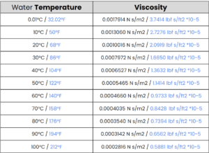
Besides pipe size, other factors that can affect pressure drop in a water pipe system include the type of pipe material, the number and type of fittings and valves used, the layout and configuration of the piping network, and the fluid properties such as viscosity and temperature.
These factors influence the frictional losses experienced by the fluid as it flows through the pipes.
Can h2x assist in improving pipe sizing based on different design parameters, and how does it achieve this?
h2x software can assist in enhancing pipe sizing based on different design parameters by automating velocity and pressure calculations and providing insights into the performance of the piping system.
It achieves this by utilising engineering principles and algorithms to analyse the layout and sizing of the pipes, taking into account factors such as fluid flow rates, pipe materials, and system constraints.
Through its intuitive interface and powerful simulation capabilities, h2x enables engineers to efficiently design and improve water pipe systems to meet project requirements.
Meet the author

h2x Team
h2x write about heat loss calculations, HVAC design workflows, and MEP software tools that help teams design faster and more accurately.
Article Last Updated: May 8, 2026