Calculating Heat Loss: A Step-by-Step Guide
Learn how to calculate heat loss using U-values, surface areas, temperature differences, ventilation and thermal bridging.
Download your free PDF of this article below.
Heat loss refers to the amount of heat energy that escapes from a building or a home, usually through doors, windows, floors, walls, and the roof.
In simple terms, the lower the heat loss, the less energy you need to keep your building warm. Calculating heat loss correctly allows for proper heating system design and can make a building more energy efficient and reduce heating bills.
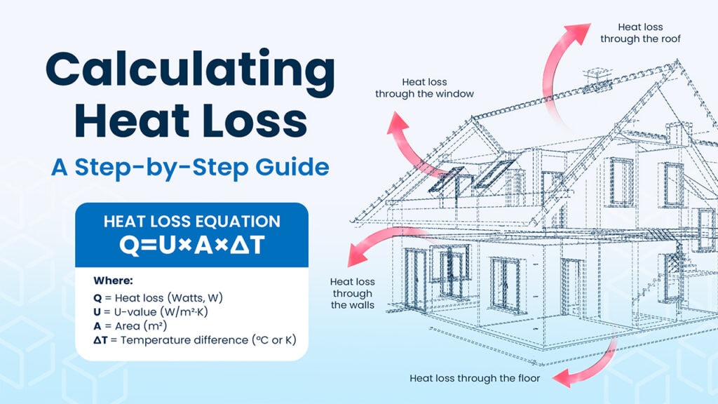
Quick answer: Heat loss is calculated by adding the heat transferred through each part of the building envelope to the heat lost through ventilation and uncontrolled air leakage. For an individual building element, the basic formula is:
Q = U × A × ΔT
where Q is heat loss, U is thermal transmittance, A is surface area and ΔT is the temperature difference across the element.
Why is Calculating Heat Loss Important?
- Accurate heat loss calculations allow heating systems to be designed and sized correctly.
- They help improve energy efficiency by avoiding unnecessary heating capacity and energy use.
- They can also identify areas of a building where insulation, glazing or air tightness could be improved.
What Do You Need to Calculate Heat Loss?
| Input | What it determines |
|---|---|
| Building or room dimensions | Surface areas and volume |
| Building element construction | Thermal performance |
| U-values | Rate of transmission through each element |
| Indoor design temperature | Required indoor condition |
| Outdoor design temperature | External design condition |
| Adjacent or ground temperatures | Heat flow through non-external surfaces |
| Ventilation rate | Planned outdoor-air heat loss |
| Infiltration rate | Heat loss caused by uncontrolled air leakage |
| Thermal bridge data | Additional losses at junctions |
How to Calculate Heat Loss Step by Step
A building heat loss calculation starts by identifying each surface through which heat can be transferred, determining its area and U-value, and calculating the temperature difference across it.
Transmission heat loss is then combined with losses caused by ventilation, infiltration and thermal bridging.
Step 1: Calculate Transmission Heat Loss
Each building element, such as a wall, roof, floor, window or door, has a U-value that represents how readily heat passes through it. Transmission heat loss should be calculated separately for each building element using the basic formula:
Q = U × A × ΔT
where:
Q= heat loss (W)U= thermal transmittance (W/m²·K)A= surface area (m²)ΔT= temperature difference across the building element (°C or K)
The result gives the rate of heat loss through that building element in watts.
Step 2: Calculate Ventilation and Infiltration Heat Loss
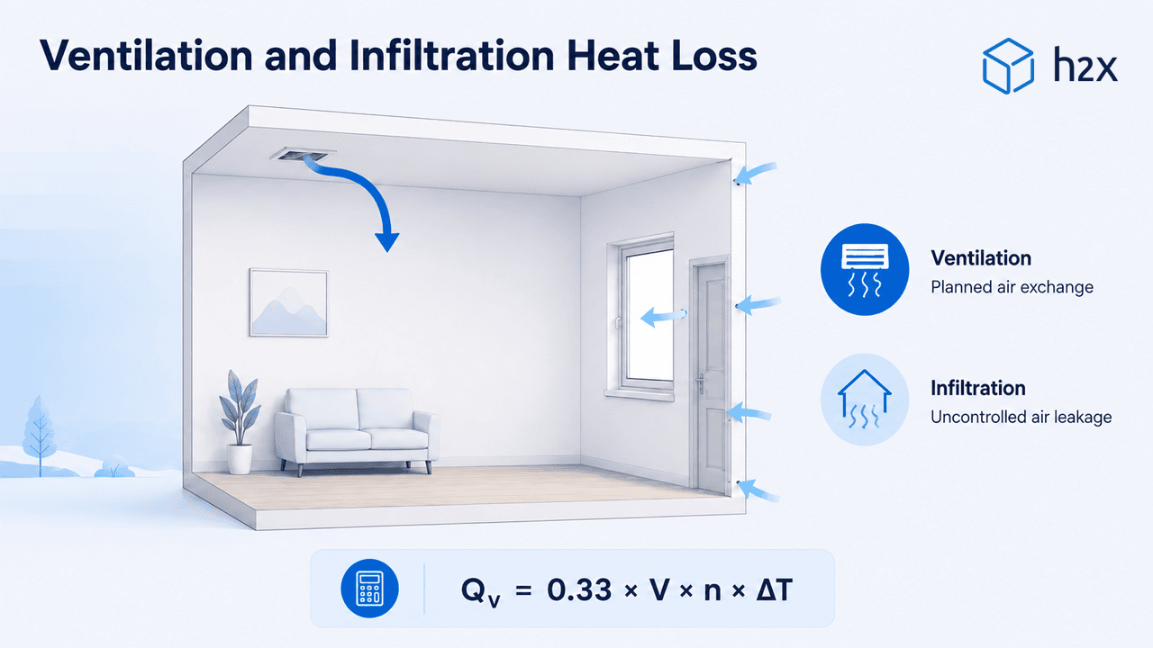
Ventilation and infiltration heat losses occur when warm indoor air is replaced by colder outdoor air. Ventilation refers to planned air exchange, while infiltration is uncontrolled air leakage through the building envelope.
Under a simplified air change method, the heat loss can be calculated using:
Qᵥ = 0.33 × V × n × ΔT
where:
Qᵥ= ventilation and infiltration heat loss (W)V= room volume (m³)n= total air change rate from ventilation and infiltration (ACH)ΔT= temperature difference between indoor and outdoor design conditions (°C or K)
The factor 0.33 represents the approximate volumetric heat capacity of air when the air change rate is expressed per hour.
Note: This is a simplified method for calculating ventilation and infiltration heat loss. Standards such as EN 12831-1:2017 use their own methodology and should be followed where required by the project.
Step 3: Account for Thermal Bridging
Another key factor to consider is thermal bridging, which occurs at parts of the building envelope where heat flows more readily than through the surrounding construction. Common examples include wall to floor junctions, roof junctions, structural elements, and the edges of windows and doors.
Thermal bridging should be included in the total heat loss. Depending on the calculation method being used, it may be calculated from individual thermal bridges using linear thermal transmittance (ψ-values), or represented using an additional thermal bridging allowance.
In the simplified example below, a percentage allowance is applied to the calculated transmission heat loss.
Step 4: Calculate Total Heat Loss
For this simplified method, total heat loss can be expressed as:
Total Heat Loss = Transmission Heat Loss + Ventilation/Infiltration Heat Loss + Thermal Bridging Heat Loss
Depending on the required calculation standard, additional factors or allowances may also need to be considered.
Try our free Heat Loss Calculator to estimate building heat loss using surface area, U-values, air changes and design temperatures.
Calculating Heat Loss: Example
The following simplified example shows how the formulas above can be used to estimate the heat loss of a single zone building. For simplicity, the same design temperature difference is applied to each building element. Real projects may require different temperatures and calculation methods for ground contact or adjacent surfaces.
Building Information
| Input | Metric | Imperial |
|---|---|---|
| Length | 5 m | 16.4 ft |
| Width | 4 m | 13.1 ft |
| Height | 2.5 m | 8.2 ft |
| Room volume | 50 m³ | 1,766 ft³ |
| Gross external wall area | 45 m² | 484.4 ft² |
| Window area | 4 m² | 43.1 ft² |
| Door area | 2 m² | 21.5 ft² |
| Net external wall area | 39 m² | 419.8 ft² |
| Roof area | 20 m² | 215.3 ft² |
| Floor area | 20 m² | 215.3 ft² |
| Indoor design temperature | 21°C | 69.8°F |
| Outdoor design temperature | −3°C | 26.6°F |
| Temperature difference | 24°C / 24 K | 43.2°F |
| Total air change rate | 0.5 ACH | 0.5 ACH |
Imperial values are rounded conversions of the metric values used in the calculation.
U-Values Used in the Example
| Building element | U-value (SI) | U-factor (Imperial) |
|---|---|---|
| External wall | 0.30 W/m²·K | 0.053 BTU/hr·ft²·°F |
| Window | 1.60 W/m²·K | 0.282 BTU/hr·ft²·°F |
| External door | 1.50 W/m²·K | 0.264 BTU/hr·ft²·°F |
| Roof | 0.25 W/m²·K | 0.044 BTU/hr·ft²·°F |
| Floor | 0.25 W/m²·K | 0.044 BTU/hr·ft²·°F |
These U-values are illustrative values used for this worked example and should not be treated as default design values.
Step 1: Calculate Transmission Heat Loss
| Element | Calculation | Heat loss |
|---|---|---|
| External walls | 0.30 × 39 × 24 | 280.8 W / 958 BTU/hr |
| Windows | 1.60 × 4 × 24 | 153.6 W / 524 BTU/hr |
| Door | 1.50 × 2 × 24 | 72 W / 246 BTU/hr |
| Roof | 0.25 × 20 × 24 | 120 W / 409 BTU/hr |
| Floor | 0.25 × 20 × 24 | 120 W / 409 BTU/hr |
| Total | 746.4 W / 2,547 BTU/hr |
Step 2: Calculate Ventilation and Infiltration Heat Loss
Using the simplified ventilation and infiltration formula:
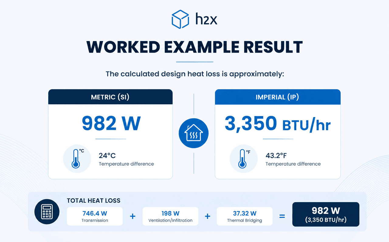
Qᵥ = 0.33 × 50 × 0.5 × 24 = 198 W
The ventilation and infiltration heat loss is therefore 198 W (approximately 676 BTU/hr).
Step 3: Apply the Thermal Bridging Allowance
Applying the 5% thermal bridging allowance:
746.4 × 0.05 = 37.32 W
Thermal bridging therefore adds 37.32 W (approximately 127 BTU/hr).
Step 4: Calculate the Total Heat Loss
The total heat loss is:
746.4 + 198 + 37.32 = 981.72 W
Rounded to the nearest watt, the calculated design heat loss is 982 W (approximately 3,350 BTU/hr).
Note: This simplified example is intended to demonstrate the heat loss calculation process. Real projects may require different design temperatures for individual surfaces, more detailed ground heat loss calculations, project-specific ventilation and infiltration rates, and different methods for accounting for thermal bridging depending on the applicable standard.
How to Reduce Heat Loss
- Improve building insulation: Proper insulation is one of the most effective ways to reduce heat loss through walls, roofs and floors.
- Upgrade your windows: Double-glazed or triple-glazed windows can significantly reduce heat loss.
- Seal any air leakage: Make sure doors and windows are properly sealed to prevent uncontrolled air leakage.
- Install a heat recovery system: Heat recovery ventilation systems can recover heat from outgoing air and transfer it to incoming air, reducing ventilation heat loss.
Common Heat Loss Calculation Mistakes
- Using the wrong U-value: Use the U-value of the complete building element rather than the thermal conductivity of an individual material.
- Using the same temperature difference for every surface: A wall facing outdoors may have a different temperature difference from a floor facing the ground or a wall adjoining a conditioned space.
- Forgetting windows and doors: Openings need to be separated from the opaque wall area to avoid double-counting.
- Ignoring infiltration: Uncontrolled air leakage can contribute significantly to heat loss.
- Ignoring thermal bridges: Junctions between building elements can increase transmission beyond the basic planar U-value calculation.
- Adding arbitrary safety margins too early: Calculate the actual design heat loss first, then apply any appropriate design or spare-capacity allowance according to the project methodology.
Heat Loss Calculation Standards
The principles behind heat loss calculations are broadly similar worldwide, but the exact methodology, design temperatures, ventilation assumptions and thermal bridge treatment can vary according to the project location and required standard.
Engineers should therefore use the method specified for the project and applicable local requirements. For example, EN 12831-1:2017 provides a specific methodology for design heating load calculations and differs from the simplified ventilation calculation shown earlier in this guide.
ASHRAE also provides guidance for design heat load calculations, including the selection of indoor and outdoor design conditions, transmission losses through building elements, and infiltration and outdoor air loads.
U-Value vs R-Value
U-value and R-value both describe thermal performance, but from opposite perspectives.
R-value measures thermal resistance: a higher R-value means greater resistance to heat flow.
U-value measures thermal transmittance: a lower U-value means less heat passes through the building element.
For a complete building element or assembly, U-value is the reciprocal of the total thermal resistance when compatible units are used:
U = 1 / R
When calculating heat loss using Q = U × A × ΔT, it is the U-value of the complete building element that is required. CIBSE guidance similarly defines U-value as the thermal transmittance of a building component and uses its area and U-value when determining heat transfer through the building envelope.
h2x’s free online R-value calculator can calculate thermal resistance using material type, thickness, thermal conductivity and multiple construction layers.
Example U-Values for Building Elements
U-values describe heat transfer through complete building elements or assemblies. The values below are illustrative examples and should not be treated as default design values, as actual U-values depend on the complete construction, materials, thicknesses and project requirements.
| Building element | Construction | U-value (SI) | U-factor (Imperial) |
|---|---|---|---|
| Wall | Solid brick | 2.10 W/m²·K | 0.370 BTU/hr·ft²·°F |
| Wall | Insulated solid brick | 0.28 W/m²·K | 0.049 BTU/hr·ft²·°F |
| Wall | Uninsulated cavity wall | 1.30 W/m²·K | 0.229 BTU/hr·ft²·°F |
| Wall | Insulated cavity wall | 0.55 W/m²·K | 0.097 BTU/hr·ft²·°F |
| Wall | Solid stone | 2.25 W/m²·K | 0.396 BTU/hr·ft²·°F |
| Wall | Insulated solid stone | 0.32 W/m²·K | 0.056 BTU/hr·ft²·°F |
| Wall | Solid concrete | 3.00 W/m²·K | 0.528 BTU/hr·ft²·°F |
| Wall | Insulated solid concrete | 0.31 W/m²·K | 0.055 BTU/hr·ft²·°F |
| Door | Solid wood | 3.00 W/m²·K | 0.528 BTU/hr·ft²·°F |
| Door | Single-glazed wood | 5.70 W/m²·K | 1.004 BTU/hr·ft²·°F |
| Door | Double-glazed wood | 3.40 W/m²·K | 0.599 BTU/hr·ft²·°F |
| Door | Triple-glazed wood | 2.60 W/m²·K | 0.458 BTU/hr·ft²·°F |
| Door | Single-glazed metal | 5.70 W/m²·K | 1.004 BTU/hr·ft²·°F |
| Door | Double-glazed metal | 3.40 W/m²·K | 0.599 BTU/hr·ft²·°F |
| Door | Triple-glazed metal | 2.60 W/m²·K | 0.458 BTU/hr·ft²·°F |
| Window | Single-glazed metal frame | 5.70 W/m²·K | 1.004 BTU/hr·ft²·°F |
| Window | Double-glazed metal frame | 3.40 W/m²·K | 0.599 BTU/hr·ft²·°F |
| Window | Triple-glazed metal frame | 2.60 W/m²·K | 0.458 BTU/hr·ft²·°F |
| Window | Single-glazed wood frame | 4.80 W/m²·K | 0.845 BTU/hr·ft²·°F |
| Window | Double-glazed wood frame | 2.80 W/m²·K | 0.493 BTU/hr·ft²·°F |
| Window | Triple-glazed wood frame | 2.10 W/m²·K | 0.370 BTU/hr·ft²·°F |
| Window | Single-glazed PVC frame | 4.80 W/m²·K | 0.845 BTU/hr·ft²·°F |
| Window | Double-glazed PVC frame | 2.80 W/m²·K | 0.493 BTU/hr·ft²·°F |
| Window | Triple-glazed PVC frame | 2.10 W/m²·K | 0.370 BTU/hr·ft²·°F |
Example Thermal Conductivity of Building Materials
Thermal conductivity and U-value are not the same measurement. Thermal conductivity describes how readily heat passes through an individual material, while U-value describes heat transfer through a complete building element or assembly. The thickness and combination of materials therefore affect the overall U-value.
| Material | Category | Thermal conductivity (SI) | Thermal conductivity (Imperial) |
|---|---|---|---|
| Plasterboard | Wall | 0.16 W/m·K | 0.092 BTU/hr·ft·°F |
| Hardwood | Wall | 0.18 W/m·K | 0.104 BTU/hr·ft·°F |
| Softwood | Wall | 0.13 W/m·K | 0.075 BTU/hr·ft·°F |
| Concrete | Floor | 1.35 W/m·K | 0.780 BTU/hr·ft·°F |
| Steel | Floor | 50 W/m·K | 28.889 BTU/hr·ft·°F |
| Screed | Floor | 1.20 W/m·K | 0.693 BTU/hr·ft·°F |
| Softwood | Floor | 0.13 W/m·K | 0.075 BTU/hr·ft·°F |
| Hardwood | Floor | 0.18 W/m·K | 0.104 BTU/hr·ft·°F |
| Wood blocks | Floor | 0.14 W/m·K | 0.081 BTU/hr·ft·°F |
| Aerated concrete | Roof | 0.16 W/m·K | 0.092 BTU/hr·ft·°F |
| Asphalt | Roof | 0.50 W/m·K | 0.289 BTU/hr·ft·°F |
| Felt/bitumen | Roof | 0.30 W/m·K | 0.173 BTU/hr·ft·°F |
| Screed | Roof | 0.41 W/m·K | 0.237 BTU/hr·ft·°F |
| Stone chippings | Roof | 0.96 W/m·K | 0.555 BTU/hr·ft·°F |
| Clay tiles | Roof | 1.00 W/m·K | 0.578 BTU/hr·ft·°F |
| Concrete tiles | Roof | 1.50 W/m·K | 0.867 BTU/hr·ft·°F |
| Wood wool | Roof | 0.10 W/m·K | 0.058 BTU/hr·ft·°F |
Thermal conductivity can vary according to material specification, density, moisture content and other properties. Use manufacturer or project-specific data where available.
Conclusion
Calculating heat loss accurately is essential for designing and sizing an efficient heating system.
Transmission through the building envelope, ventilation, infiltration and thermal bridging all contribute to the final design heat loss. Using accurate building data and the appropriate calculation methodology helps avoid both undersizing and unnecessary oversizing.
For engineering projects, always use the calculation standard and design conditions required for the building and its location.
Calculate Heat Loss with h2x
Manual heat loss calculations become harder to maintain as a project changes. Updating a room size, building construction, U-value or design temperature can require multiple calculations to be checked again.
h2x connects heat loss calculations directly to the building and heating system design, allowing transmission, ventilation, infiltration and thermal bridging results to update as project inputs change.
Stop calculating heat loss by hand.
h2x automatically calculates transmission, ventilation, infiltration and thermal bridging losses as you design, with results updating whenever the project changes. No manual formulas or spreadsheets.
Frequently Asked Questions (FAQs)
How do you calculate heat loss in a building?
Building heat loss is calculated by adding the heat lost through the building envelope to losses caused by ventilation, infiltration and thermal bridging. Transmission heat loss is calculated separately for building elements such as walls, roofs, floors, windows and doors before the results are combined.
What is the basic heat loss formula?
For an individual building element, the basic heat loss formula is:
Q = U × A × ΔT
Where Q is heat loss, U is thermal transmittance, A is surface area and ΔT is the temperature difference across the building element.
What does U-value mean in a heat loss calculation?
U-value measures how readily heat passes through a complete building element, such as a wall, roof, floor, window or door. A lower U-value indicates less heat transfer and therefore lower transmission heat loss for the same surface area and temperature difference.
How do you calculate ventilation and infiltration heat loss?
Under a simplified metric air change method, ventilation and infiltration heat loss can be calculated using:
Qᵥ = 0.33 × V × n × ΔT
Where V is room volume, n is the total air change rate and ΔT is the indoor to outdoor temperature difference. Where a specific calculation standard applies, its required methodology should be used instead.
What is the difference between heat loss and heat load?
Heat loss describes the rate at which heat leaves a building or space under a given set of conditions. The design heating load is the heating capacity required to offset those losses and maintain the required indoor design temperature under defined design conditions.
How does thermal bridging affect heat loss?
Thermal bridges create areas where heat flows more readily through the building envelope, increasing overall transmission heat loss. Depending on the calculation method, thermal bridging may be calculated using linear thermal transmittance (ψ-values) or represented by an additional thermal bridging allowance.
Should heat loss be calculated room by room?
Room-by-room heat loss calculations are often required when sizing individual heat emitters or designing heating zones. A whole building calculation can also be used to determine overall heat loss or heating demand, depending on the project and calculation methodology.
What temperature should be used for a heat loss calculation?
Heat loss calculations should use the indoor and outdoor design temperatures required for the project rather than the current outdoor temperature. The appropriate outdoor design condition depends on the building location and applicable calculation standard or design methodology.
Meet the author

Daniel Mousdell
Daniel Mousdell is a Digital Marketer at h2x, where he creates technical content and resources for HVAC and MEP engineers. Outside of work, he runs LilWayneHQ.
Article Last Updated: August 21, 2026