
6 Hot Water System Design Considerations for Recirculation
Six practical checks for circulated hot water systems, from pipe routing and circulation flow to pressure loss, balancing and pump duty.
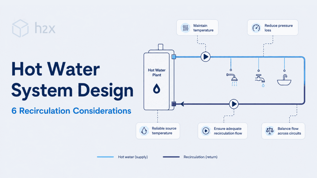
Good commercial hot water system design is not only about getting heated water from the plant to the outlets. Where the design includes recirculation, the pipework also needs to maintain suitable temperatures around the network without creating unnecessary flow, pressure loss or energy use.
That becomes more challenging as the system grows. Multiple branches can have different heat losses and hydraulic resistance, while changes to pipe size can affect velocity, heat loss and the balancing required elsewhere.
The six considerations below focus on the circulation side of hot water system design, from planning the pipework through to establishing the recirculation pump duty.
If you are looking for a broader introduction to how recirculation works, including system types, controls and pump sizing, see our hot water recirculating pump guide.
1. Keep the Hot Water System Layout Simple
Keeping the layout simple sounds obvious, but complexity can creep into a design surprisingly quickly.
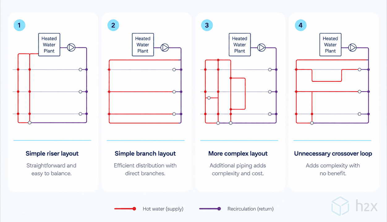
Designers may add extra connections for redundancy or flexibility with good intentions. However, circuits branching from other circuits and unnecessary interconnections can make it much harder to predict how circulation flow will move through the system.
Water naturally favours routes with lower hydraulic resistance. As designers introduce more alternative paths, balancing those routes becomes more complicated.
That does not mean every hot water system needs to follow the same arrangement. Building geometry, redundancy requirements and project standards will influence the final design. The important point is that every additional circulation path should have a clear purpose.
Ideally, each circuit should be easy to identify, calculate, balance and commission.
The diagram below illustrates why a straightforward circulation arrangement is usually easier to manage than a heavily interconnected one.
2. Check the Correct Design Flow Conditions
A circulated hot water system does not operate under one hydraulic condition all the time.
When occupants use fixtures, the supply pipework needs to carry the required draw-off flow. During periods with little or no demand, the recirculation system still needs enough flow to offset distribution heat loss and maintain the intended water temperatures.
Both conditions matter during hot water system design.
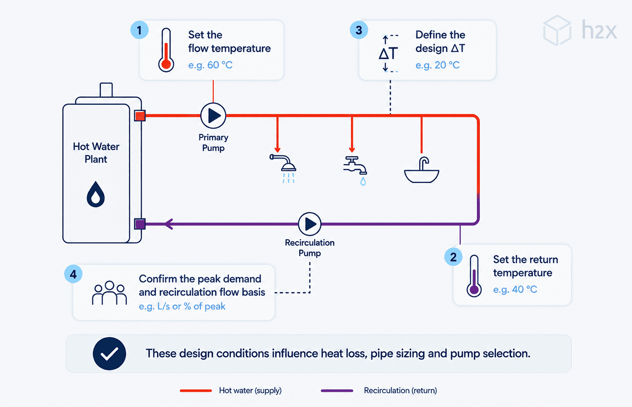
For the circulation side of the system, the required flow depends on the heat loss the system needs to offset and the permitted temperature difference.
The basic relationship is:
Heat Loss = Mass Flow Rate × Specific Heat Capacity × ΔT
Rearranging it gives:
Mass Flow Rate = Heat Loss ÷ (Specific Heat Capacity × ΔT)
For the same heat loss, a smaller permitted temperature difference requires a higher circulation flow.
Do not treat fixture demand and circulation flow as interchangeable values. The applicable design method and project standards determine how designers should check the different operating conditions when sizing each section of pipework.
Some methods may require designers to consider circulation flow alongside draw-off flow in relevant parts of the system. Rather than applying one universal rule, the calculation should follow the standard and system arrangement being used for the project.
This can make pipe sizing iterative. Changing the pipe diameter affects velocity and heat loss, while a change in heat loss can alter the circulation flow required.
3. Distribute Circulation Flow According to Heat Loss
Calculating the total recirculation flow is only part of the job. You also need to distribute that flow appropriately around the system.
Not every circuit loses the same amount of heat.
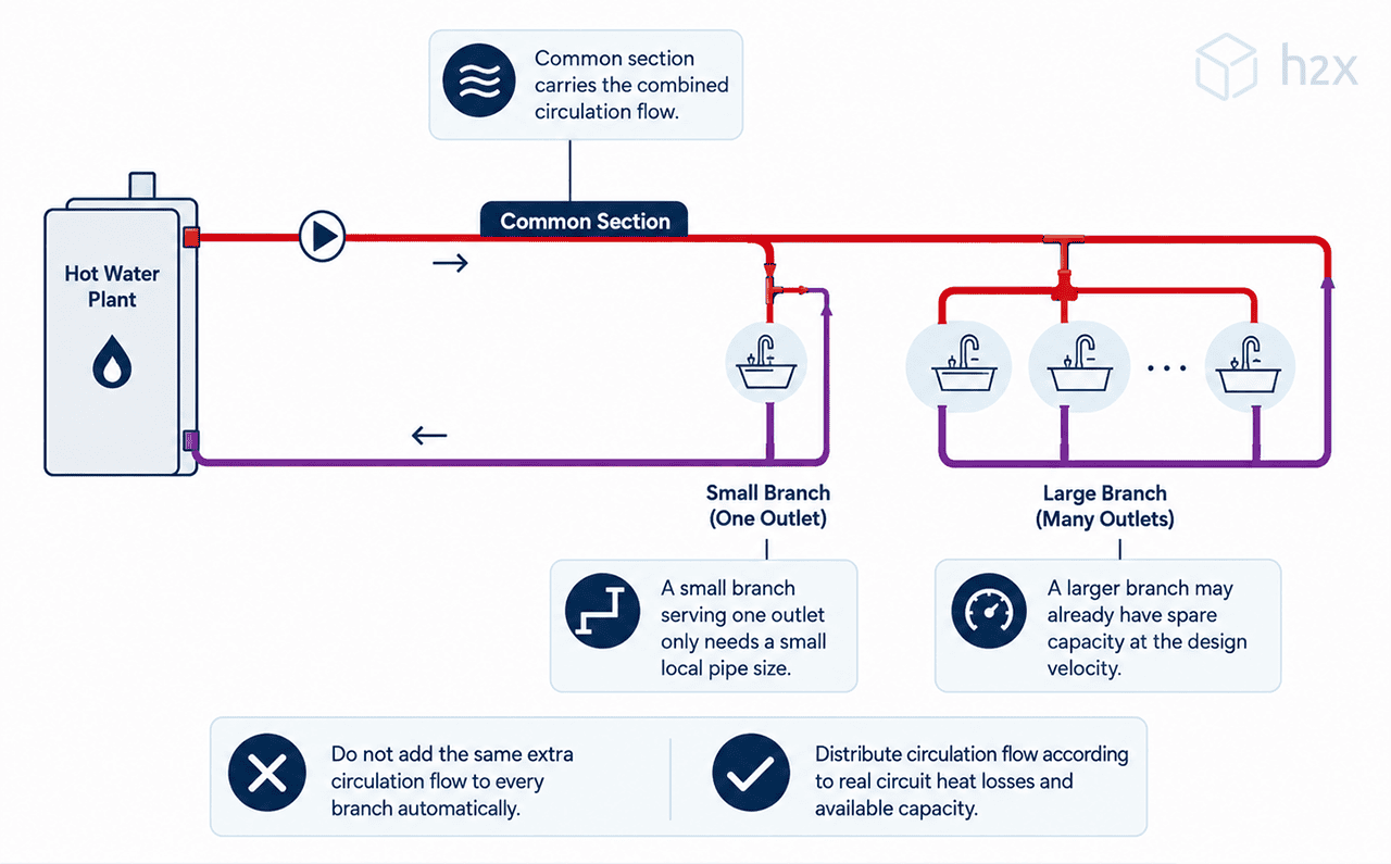
Pipe length, diameter, insulation, water temperature and surrounding conditions can all change the heat loss from one part of the network to another. A long branch may therefore need more circulation flow than a shorter, well-insulated route.
Simply dividing the total flow equally between every circuit can give the wrong result.
Instead, distribute the flow according to the heat the system needs to offset throughout the circulated pipework.
ASPE describes a heat loss-based approach to domestic hot water circulation that relates each circuit’s flow to its share of the system heat loss.
This becomes especially important where several circuits share common pipe sections. Those common sections need to carry the circulation flow associated with the branches they serve, while the flow should divide appropriately as the network separates.
The aim is not simply to increase pipe sizes whenever the system carries more flow.
Larger pipes hold more water and have greater external surface area, which can increase system volume and distribution heat loss.
Pipe sizing therefore needs to balance the required flow with velocity, pressure loss, material requirements and the applicable project criteria.
The example below shows why it is worth considering where the circulation flow is distributed rather than allowing it to follow one route by assumption.
4. Calculate Pressure Loss Along Each Circulation Circuit
Once you know the required flows, calculate the hydraulic resistance through the circulation system.
Pressure loss can come from:
- Straight pipework
- Elbows and other fittings
- Isolation valves
- Balancing valves
- Check valves
- Heat exchangers and equipment
- Other components in the circulation path
With several parallel circuits, do not simply add their individual pressure losses together.
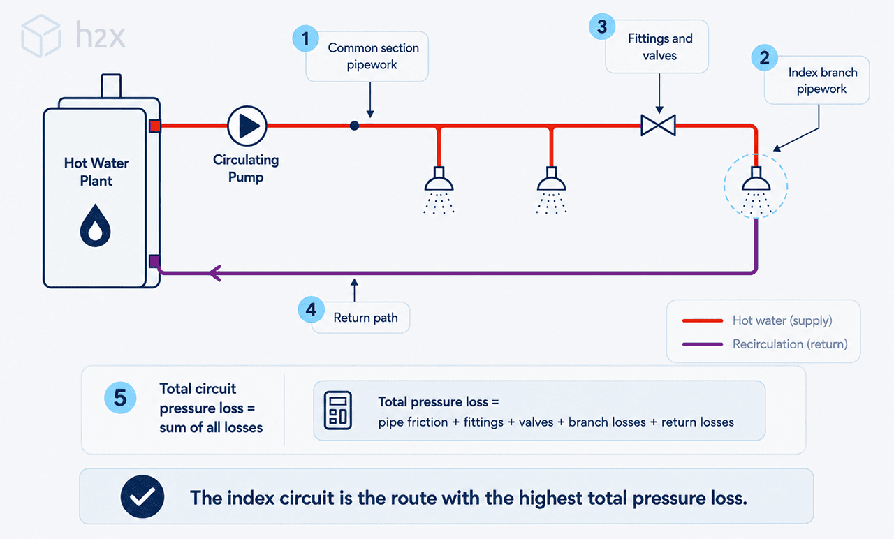
Instead, calculate the pressure loss along each complete circulation route. Engineers commonly call the path with the greatest relevant pressure loss at the design condition the index circuit, or the hydraulically most demanding circuit.
That route normally helps establish the pump head the system requires.
The index circuit is not necessarily the circuit physically furthest from the hot water plant. A shorter path containing smaller pipes, more fittings or more restrictive components may have a greater pressure loss than a longer route.
This distinction matters because adding the pressure losses of several parallel branches together would overstate the head required from the recirculation pump.
You can use our free pressure drop calculator when checking pipe pressure losses.
For a deeper explanation of pump flow, head and index circuits, see our recirculation pump sizing and selection guide.
5. Balance the Hot Water Recirculation System
Finding the index circuit does not mean the rest of the system will automatically receive the correct circulation flow.
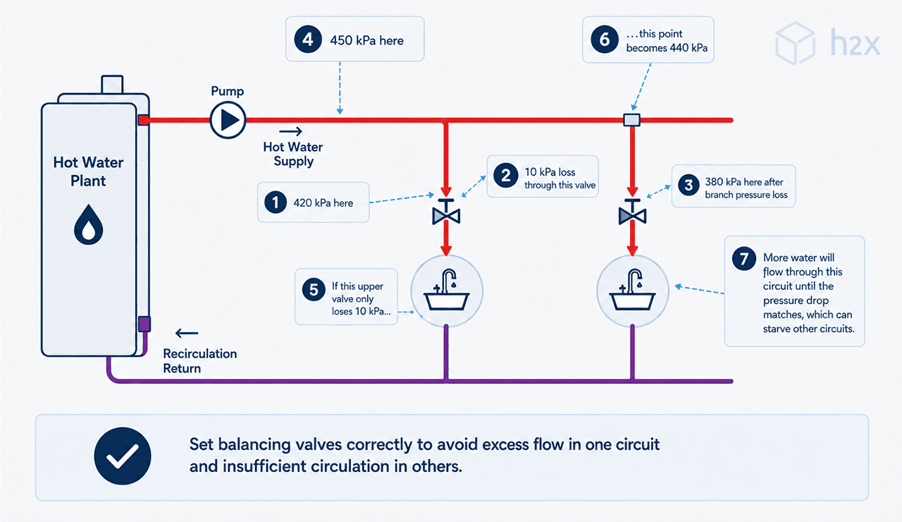
Without balancing, water tends to favour the circuits with lower hydraulic resistance. One branch may receive more flow than it needs while a more resistant route receives too little.
The result can be uneven temperatures around the system.
Balancing valves introduce controlled resistance into the lower-resistance circuits so the system distributes the required circulation flow more effectively.
The image below shows balancing valves within a multi-circuit recirculation arrangement.
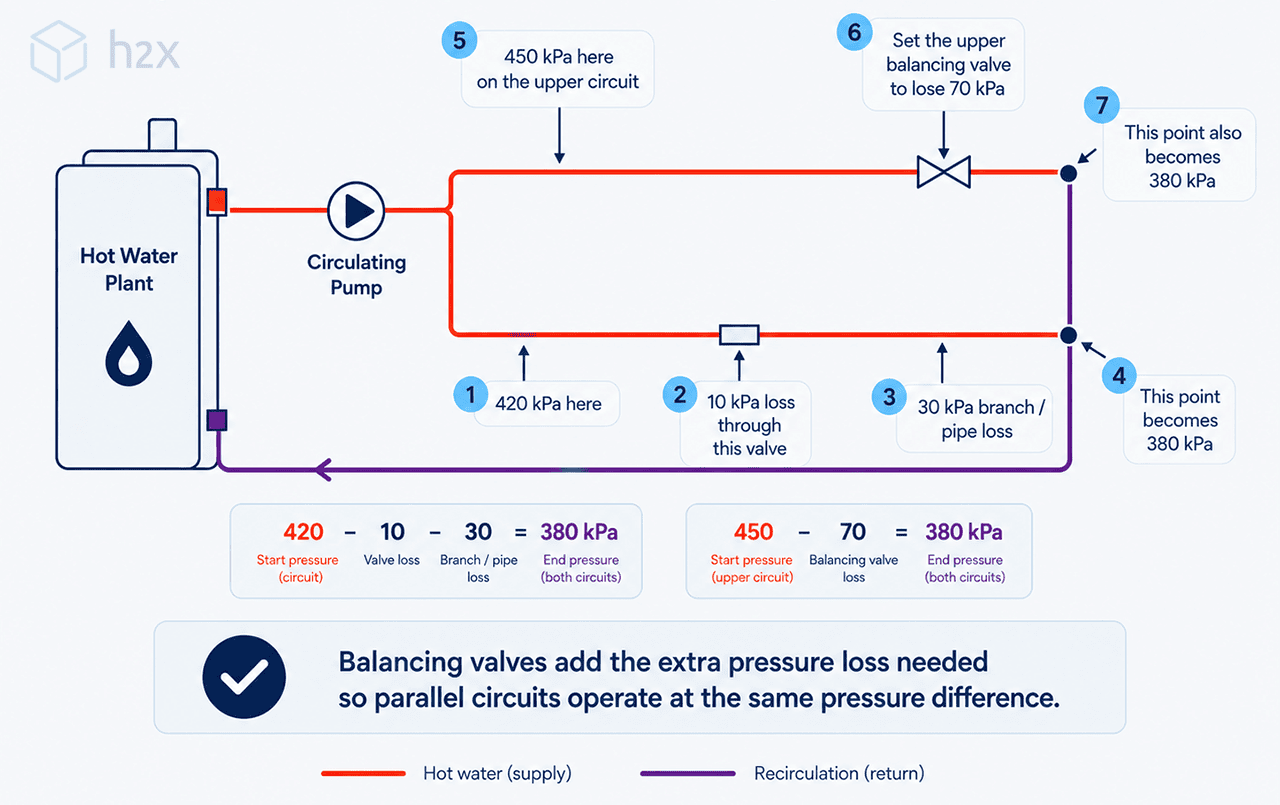
The amount of resistance required will not normally be identical at every valve.
Each circuit already has its own natural pressure loss. A relatively easy circuit needs more additional resistance than a circuit whose hydraulic resistance is already close to the system’s most demanding route.
This means balancing is based on the relationship between the required circuit flow and the pressure loss around each route, rather than applying the same valve setting everywhere.
The following diagram illustrates how different balancing requirements can apply where circulation circuits reconnect.
Valve location should also consider manufacturer guidance, accessibility, commissioning requirements and the specific system arrangement. There is no need to force one valve location rule onto every project.
On taller buildings, the circulation design may also interact with static pressure, PRVs and pressure zoning. Those issues are covered separately in our guide to hot water recirculation design for high-rise buildings.
6. Match the Recirculation Pump to the System Duty
Once you know the circulation flow and relevant system pressure loss, combine them to establish the required pump duty.
The two key values are:
- Flow (Q): The circulation flow the system requires
- Head (H): The hydraulic resistance the pump needs to overcome at that flow
Do not select a pump from flow alone.
A model may be capable of providing the required flow against very little resistance, yet be unable to maintain the same flow once it is connected to the real system.
Therefore, compare the calculated flow and head together against the manufacturer’s pump curve.
Check the Pump Operating Point
The pump and system curves interact to determine the actual operating point. This is where the flow and head produced by the pump match the resistance of the system.
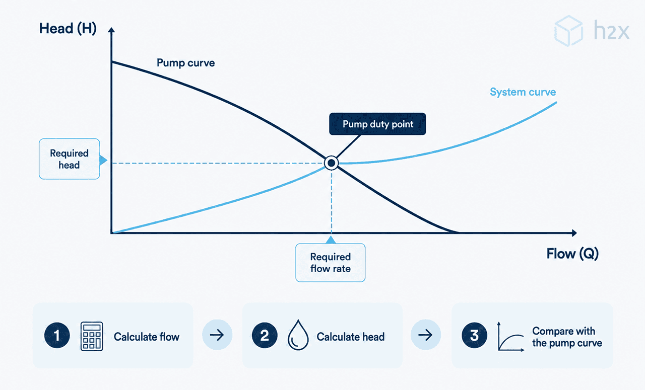
Ideally, the selected pump should operate appropriately around the required duty point rather than providing substantially more or less flow than the system needs.
Too much flow can increase velocity, noise, differential pressure and pump energy use. Too little flow can prevent some circulation routes from maintaining their required conditions.
Changes to system resistance can also move the operating point. Balancing valves add the resistance needed to balance individual circuits, but they should not be used simply to force an unsuitable pump to match the system.
The selected pump and control strategy should instead suit the calculated system duty and the operating conditions expected in practice.
Where a pump has multiple speed settings or variable speed control, the selected operating mode also matters. A correctly sized pump can still produce poor results if the installer commissions it on an inappropriate setting.
For more detail on the differences between pump control types, see our guide to fixed and variable speed pumps.
Bringing the Hot Water System Design Together
The difficult part of circulated hot water design is that none of these calculations sits completely on its own.
Change a pipe size and the velocity and pressure loss change with it. Alter the insulation and the heat loss can change, which affects the circulation flow. That revised flow may then influence pipe sizing, balancing and the required pump duty.
On a simple system, working through those relationships manually may be manageable. On a larger commercial system with several branches and circulation circuits, the iterations can quickly build up.
A better workflow keeps the layout, hydraulic calculations and thermal calculations connected as the design develops.
h2x allows engineers to create the hot water system layout while calculating results such as pipe sizes, circulation flow, heat loss, pressure loss, balancing requirements and recirculation pump duty within the same project.
If you want to see that process in the software, our hot water recirculation system design workflow in h2x walks through it step by step.
Design hot water systems in one connected workflow
Create the system layout while reviewing pipe sizing, circulation flow, heat loss, pressure loss and balancing as the design develops.
Frequently Asked Questions
What Should You Consider When Designing a Hot Water System?
Key hot water system design considerations include the pipe layout, fixture demand, circulation flow, distribution heat loss, pressure loss, balancing and recirculation pump duty. The design should also follow the applicable temperature, pipe material, water quality and project requirements.
How Is Hot Water Recirculation Flow Calculated?
Hot water recirculation flow is commonly determined from the heat loss that the circulation system needs to offset and the permitted temperature difference. For the same heat loss, a smaller temperature difference requires a higher circulation flow.
How Should Recirculation Flow Be Distributed Between Circuits?
Circulation flow should reflect the heat loss associated with the different parts of the network rather than automatically being divided equally. Pipe length, diameter, insulation, water temperature and surrounding conditions can all affect the amount of heat lost from a circuit.
What Is the Index Circuit in a Hot Water System?
The index circuit is the complete circulation route with the greatest relevant pressure loss at the design condition. It normally helps establish the required recirculation pump head and is not necessarily the circuit physically furthest from the hot water plant.
Why Does a Hot Water Recirculation System Need Balancing?
Parallel circulation circuits can have different hydraulic resistance, causing water to favour easier flow paths. Balancing introduces controlled resistance into lower-resistance circuits so the required circulation flow can be distributed more effectively throughout the system.
How Do You Select a Hot Water Recirculation Pump?
Calculate the required circulation flow and the pump head needed to overcome the relevant system pressure loss. Together, these values form the required duty point, which can then be compared with manufacturer pump curves and the expected operating range.
Meet the author

Jonathan Mousdell
Jonathan Mousdell is a Mechanical Engineer and co-founder of h2x, where he creates technical content and resources for MEP engineers.
Article Last Updated: August 27, 2026