How To Calculate Water Demand
Learn how to calculate the water demand in a system based on the local standard's requirements and a range of variables.

Introduction
When sizing pipes for water systems, engineers need to consider the likely consumption of water by understanding how to calculate water demand.
But, you are not required to provide a pipe system that supplies the maximum flow at any one time because all the taps won’t necessarily run at the same time.
So, instead, the plumbing system is designed to consider the probable simultaneous demand (PSD) pattern of the users.
Flow Rate Dynamics Probable Simultaneous Demand
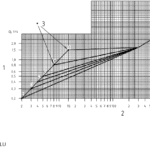
The PSD is determined by converting the loading units/full flow rate of all the fixtures that are connected downstream of the pipe, into a flow rate.
PSD is measured as a flow rate in L/s, m3/s, or GPM
The conversion from loading units/full flow rate to PSD is dependent on what conversion method the user chooses.
There are many options available, but you generally have to use the local one that is given by the regulations in your area.

h2x offers several PSD methods including:
- Australia:
- AS/NZS 3500.1
- Institute of Plumbing (Barrie’s Book)
- United States of America:
- IPC 2018
- UPC 2018
- United Kingdom:
- BS 8558
- BS 806
- CIPHE
- Europe:
- DIN 1988-300
As shown in the image above, each PSD method will give you a different result.

DIN 1988-300
To manually calculate flow rate and convert the loading units or full flow rate of all the fixtures using the DIN 1988-300:2012-05 equation, you have to use the following water demand formula:
Vs = a(Σ Vr)b – c
Where:
Vs is the peak flow rate.
Vr is the design flow rate.
a, b, c is the constants (as per the table below).

If the flow rate is below 0.2l/sec, the full flow rate is used.
If the full flow rate is higher than 500 l/sec, a flow rate result will not be provided as it exceeds the limits of the water demand formula.
AS/NZS 3500.1:2018
Dwellings:
The equation below specifies the method of sizing a typical installation in accordance with AS/NZS 3500.1:2018 for dwellings:
Flow Rate = 0.03n+0.4554√n
Loading Units:
The table below specifies the method of sizing a typical installation in accordance with AS/NZS 3500.1:2018 for loading units:

Institute of Plumbing (Barrie’s Book)
Dwellings:
The table below specifies the method of sizing a typical installation in accordance with Institute of Plumbing (Barrie’s Book) for dwellings:

Loading Units:
The table below specifies the method of sizing a typical installation in accordance with Institute of Plumbing (Barrie’s Book) for loading units:

IPC 2018
Flush Tanks:
The following table specifies the sizing methods under the International Plumbing Code for flush tanks:

Flush Valves:
The following table specifies the sizing methods under the International Plumbing Code for the flushometer:

UPC 2018
Flush Tanks:
The following table specifies the sizing methods under the Uniform Plumbing Code for flush tanks:

Flush Valves:
The following table specifies the sizing methods under the Uniform Plumbing Code for the flushometer:

BS 8558 / Institute of Plumbing / CIBSE Guide G / CIPHE
The BS8558 and the CIBSE Guide G are two of the principal flow rate methods employed in the United Kingdom commercial buildings.
The loading units take the flow rate into account and the length of time that the outlet will be in use:

BS 806
The BS 806 is one of the principal flow rate methods employed in the United Kingdom for pipe sizing in residential buildings:


How To Calculate Water Demand: Things To Consider
Diversified Flow Rates:
In some cases, the flow rate of a single fixture will exceed the flow rate provided by the probable simultaneous demand calculation.
For example, a birthing pool may have a flow rate of 1 L/sec but that will get diversified to less than 1 L/sec.
This means you need to be aware of the pipe sizing, velocity, and pressure loss calculations in that pipe and potentially make some modification.
Continuous Flow Rates:
Continuous flow rates are parts of the system that will not be diversified and the system is sized for them to be on 100%.
Examples of a continuous flow rate would be a fire system, an irrigation system, etc.
Continuous flow rates are added to the probable simultaneous demand flow rates to get the total flow rate on a system:
Flow Rate = Probable Simultaneous Demand + Continuous Flow Rates
Cold Water Pipes Supplying a Heated Water Plant:
Where a cold water pipe supplies the cold water to fixtures and also the heated water plant that supplies the heated water to the same fixtures, the flow rate will usually take the largest of the two flow rates.
In certain cases, particularly in the UK and USA, combining the loading units-part of knowing how to calculate water demand-enables the simultaneous use of both hot and cold water taps in fixtures.
Volume Flow Rate:
The volumetric flow rate is the volume of the water flowing through a cross-sectional area per unit of time.
You would need to know a pipe size for the average volumetric flow rate formula.
![]()
h2x is design software built to ensure compliance, efficiency, accuracy and collaboration.
The software automates flow rate, velocity, pressure, pump duty, plant size, and recirculation system calculations, freeing you from laborious math tasks and enabling you to concentrate on your project’s design.
h2x’s straightforward user interface helps engineers produce high-quality designs and work more efficiently, all while adhering to industry regulations.
The software has already been used to size millions of kilometres of pipes in projects across the world.
Book a demo or start a free trial with h2x today to discover how we can help you improve your design and calculation workflow!
5 Reasons Industry Experts Design with H2X
- Exceptional Support
- Proven & Reliable
- Ease Of Use
- Built By The Industry
- Worldwide User Base

What's in the Pipeline?
Get technical resources delivered to your inbox weekly!