7 Important Steps for Designing Pressure Reduction Valves
It is important to size a pressure reduction valve (PRV) to suit the flow rate that passes through it. You should not necessarily match the inlet pipe size as this can lead to over-sizing of the PRV and oversizing the PRV has adverse effects on the system such as causing undesired noise and also damaging

1 – Sizing
It is important to size a pressure reduction valve (PRV) to suit the flow rate that passes through it. You should not necessarily match the inlet pipe size as this can lead to over-sizing of the PRV and oversizing the PRV has adverse effects on the system such as causing undesired noise and also damaging the PRV seal.
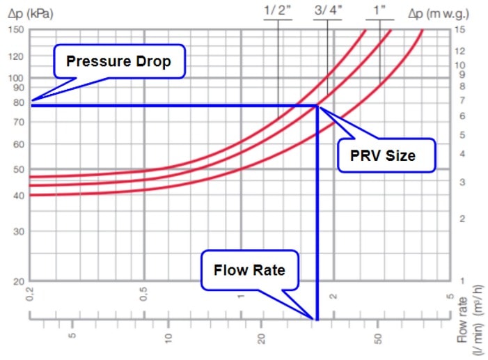
To size the PRV correctly, you need to find the technical data sheet from your preferred manufacturer and find a table that looks similar to below.
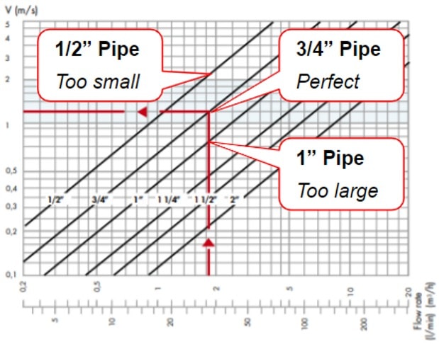
You can then plot the peak flow rate on the graph and find the corresponding PRV size. As a rule of thumb, you want to be within the 1-2 m/sec zone on the chart.
As you can see in the example above, for a flow rate of 32 l/min:
– The 1/2″ size is too small (velocity = 2.05 m/sec)
– The 3/4″ size is perfect (velocity = 1.10 m/sec)
– The 1″ size is too large (velocity = 0.75 m/sec)
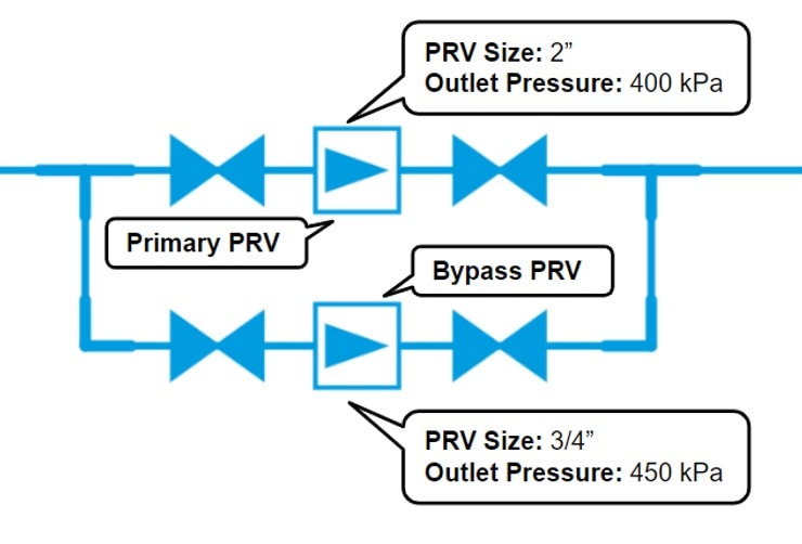
2 – Bypass
It is important that PRVs are sized to cater for low flow rates too.
Buildings rarely operate at a peak demand so they are not commonly subject to the peak flow rate. Neglecting the low flow rates will also have adverse effects on the system such as causing undesired noise and damaging the PRV seal.
As a rule of thumb, the PRV bypass should be designed for 20% of the peak flow rate and need to be set at least 50 kPa above the primary PRV.
Setting the bypass PRV to a higher pressure allows the low flow rates to take the path of least resistance and this allows the bypass PRV to be used during the non-peak demand.
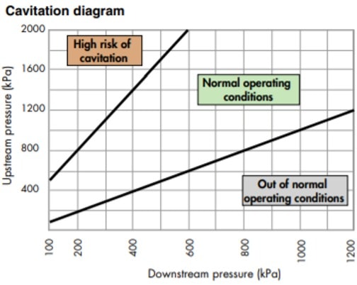
3 – Pressure Ratio
When setting the outlet pressure of the PRV, it is important to get the step-down ratio correct.
A 2:1 ratio works well e.g. 1000 kPa inlet pressure to 500 kPa outlet pressure.
If you have a ratio that is higher than 2:1, you risk cavitation which again could have adverse effects on the system such as causing undesired noise and damaging the PRV seal.
The diagram below is useful for checking the inlet and outlet pressure of the PRV design to see if it falls in the ‘normal operating conditions’ area.
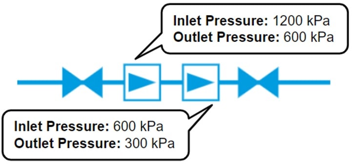
If you did need to reduce the pressure at a higher ratio such as from 1200 kPa to 300 kPa (4:1), installing an additional PRV in series is recommended as shown in the example below. This allows a 2:1 ratio to be maintained through each PRV.
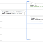
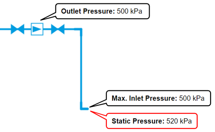
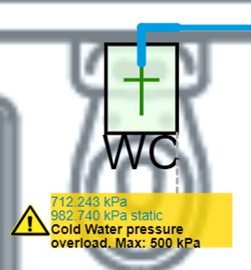
4 – Static Pressure
It is very important to consider static pressure when setting the PRV outlet pressure.
For example, as shown in the section diagram below, if you have a PRV in the ceiling and set the outlet pressure to 500 kPa, when the water gets to the outlet 2m below, the pressure will be approximately 520 kPa due to the vertical pressure gain. This consequently means that there is too much pressure at the fixture and that could lead to a non-compliant system and damaged tapware.
5 – Pressure Loss
As water flows through a PRV, pressure loss occurs and needs to be considered in the design.
The table below gives an idea of what pressure loss you can expect under different scenarios.
A flow rate of 32 l/min through a 3/4″ PRV has 80kPa pressure loss.
It is important to be aware of this in the design because 80kPa pressure loss could be the difference between supplying a compliant pressure at the fixture and a non-compliant pressure at the fixture.

6 – Material
Each material has ideal working conditions and not every PRV is suitable for all applications.
For example, if you have hot water passing through a PRV at a high velocity on a regular occasion, it would be prudent to select a stainless steel PRV. Alternate material selections could cause corrosion of the valve.
Always check with the manufacturer that the PRV you have chosen will suit the design it is being used in.
7 – Air Valves
It is recommended to install air valves downstream of PRVs.
Air valves eliminate air pockets from the system which are created under normal working conditions.
Eliminating air from the system minimises the associated consequences of pressure surges, friction loss, corrosion, and vibrations.
How can H2X help you with PRV designs?
When using H2X to design your systems:
1. You receive a warning at fixtures to indicate where PRVs are required:
2. The PRV is sized automatically, including the bypass if it is required:
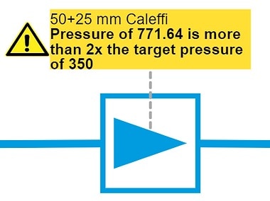
3. You receive a warning for having a step-down ratio greater than 2:1:
See how H2X works for yourself in this video:
We hope this blog helps with your next design which involves a PRV.
Please leave comments below if you have any feedback or suggestions for future blog posts!
5 Reasons Industry Experts Design with H2X
- Exceptional Support
- Proven & Reliable
- Ease Of Use
- Built By The Industry
- Worldwide User Base

What's in the Pipeline?
Get technical resources delivered to your inbox weekly!