Gas Pipe Sizing Guide: How to Size Natural Gas and LPG Pipework
A practical gas pipe sizing guide using International Fuel Gas Code (IFGC) equations, with metric and imperial units for natural gas and LPG systems.

This gas pipe sizing guide helps engineers select the correct pipe diameter for natural gas or LPG systems. When pipework is correctly sized, every appliance receives its required flow at the required inlet pressure. If pipes are undersized, appliances can be starved of gas. If pipes are oversized, projects can waste material, labour, and money.
Gas pipe sizing is the process of calculating the minimum pipe diameter needed to deliver enough natural gas or LPG to each appliance at the required pressure. The calculation depends on appliance load, gas type, pipe material, pipe length, fittings, allowable pressure drop, and the local code or standard used for the project.
This guide uses the International Fuel Gas Code (IFGC) as the worked example. It provides clear equations for low-pressure and high-pressure gas systems. However, gas pipe sizing requirements vary by country and project type, so final designs should always be checked against the applicable local standard.
Key Takeaways:
- This gas pipe sizing guide explains how to determine the correct diameter for each pipe section based on flow demand and allowable pressure drop.
- The IFGC uses two equations: one for low-pressure systems (below 1½ psi / 103 mbar) and one for high-pressure systems (at or above 1½ psi / 103 mbar).
- Equivalent pipe length must include fittings and valves, not only the straight pipe run.
- Schedule 40 black steel is commonly used for above-ground gas distribution in many commercial projects, particularly in North America.
- h2x automates gas pipe sizing across multiple pipe materials including steel, copper, stainless steel, and high-density polyethylene (HDPE).

A Basic Breakdown of Gas Pipe Sizing
Gas pipe sizing determines the minimum pipe diameter needed to deliver the required gas flow to every appliance in a building. The calculation balances three variables:
- total gas demand in cubic feet per hour (CFH) or cubic metres per hour (m³/h)
- equivalent pipe length from the gas meter to the farthest outlet
- allowable pressure drop across the system
Every appliance has a minimum inlet pressure it needs to operate correctly. For most residential gas appliances, that pressure is about 5 inches of water column (1.25 kPa). If the pipe is too small, friction along the pipe drops the pressure below that threshold. The appliance then runs poorly or fails to ignite.
Therefore, correct sizing ensures reliable appliance operation. It also meets code requirements and avoids the cost of replacing an undersized main after installation.
Common gas pipe sizing conversions
- 1 psi = 68.95 mbar
- 1½ psi = 103 mbar
- 1 inch water column = 0.249 kPa
- 0.5 inch water column = 0.125 kPa
- 1 ft = 0.305 m
- 1 inch = 25.4 mm
- 1 Btu/h = 0.293 W
Why Is Gas Pipe Sizing Important?
Incorrectly sized gas pipework causes real, measurable problems. An undersized main creates excessive pressure drop, which starves downstream appliances during peak demand. As a result, water heaters short-cycle, furnaces fail to ignite, and commercial kitchens lose burner performance at critical times.
On the other hand, oversizing creates different problems. It wastes material, adds unnecessary installation labour, and, in large systems, slows the response to changing loads. Additionally, oversized pipe means more gas volume inside the building envelope, a significant safety consideration.
Pipe sizing also drives code compliance. The IFGC and NFPA 54 require documented calculations showing every section meets the minimum flow capacity for its connected load. An incorrect sizing calculation is one of the most common reasons a gas system fails inspection or final sign-off.
Which Gas Pipe Sizing Standard Should You Use?
This gas pipe sizing guide uses the International Fuel Gas Code (IFGC) as the worked example because it provides clear sizing equations for low-pressure and high-pressure gas systems. However, gas pipe sizing requirements vary by country and project type.
In the UK, engineers commonly refer to BS 6891 for low-pressure domestic pipework and IGEM/UP/2 for industrial and commercial premises. In Europe, EN 1775 provides functional recommendations for gas pipework in buildings. And in Australia and New Zealand, gas installations are covered by AS/NZS 5601.
The underlying hydraulic principles are similar across regions, but the approved materials, pressure drops, testing requirements, safety factors, and documentation requirements can differ. Always confirm final pipe sizes against the local standard and gas network requirements.
| Region | Common Standard or Code | Typical Use |
|---|---|---|
| United States | IFGC / NFPA 54 | Fuel gas piping in buildings |
| United Kingdom | BS 6891 / IGEM/UP/2 | Domestic, commercial, and industrial gas pipework |
| Europe | EN 1775 | Functional recommendations for gas pipework in buildings |
| Australia / New Zealand | AS/NZS 5601 | Gas installation design, installation, and commissioning |
Gas Pipe Sizing in Five Steps
The standard process for sizing gas pipes uses the longest-length method described in the IFGC. Following that, you can use the below gas pipe sizing guide to work through the five steps for any new system:
- Calculate the total gas demand in cubic feet per hour (CFH) for each appliance. Divide the appliance input rating in Btu/h by the heating value of the gas, which is roughly 1,000 Btu/ft³ for natural gas. In metric regions, divide the appliance input in MJ/h by the calorific value of the gas. This is typically around 38 MJ/m³, though the exact value should be confirmed with your local gas network operator.
- Measure the longest pipe run from the meter to the farthest appliance. Add an allowance for fittings and valves to get the equivalent length used for every section in the system.
- Select the correct sizing equation based on the system’s operating pressure. Use IFGC Equation 4-1 for systems below 1½ psi (103 mbar), or IFGC Equation 4-2 for systems at 1½ psi (103 mbar) and above.
- Size each section of pipe based on the cumulative downstream load and the equivalent length from the gas meter to the farthest outlet served by that section.
- Verify the final sizes against the design criteria and confirm every appliance receives its minimum required pressure under worst-case flow.
How to Size Low-Pressure Gas Pipes Using IFGC Equation 4-1
Note: the majority of residential and light commercial gas systems operate below 1½ psi (103 mbar), the threshold separating low-pressure from high-pressure design. These systems use IFGC Equation 4-1:
Q = ( D × 19.17 × [ ΔH ÷ ( Cr × L ) ] ^ 0.206 ) ^ ( 1 ÷ 0.381 )
Where:
Qis the gas flow in CFHDis the inside diameter in inchesΔHis the allowable pressure drop in inches of water columnCris the gas-specific constant (0.6094 for natural gas), andLis the equivalent pipe length in feet
The table below shows the maximum gas flow capacity for Schedule 40 black steel pipe across common pipe sizes and equivalent lengths, based on the standard design pressure drop of 0.5 inches water column (0.125 kPa). Use it as a quick reference when checking a calculation result.

How to Size High-Pressure Gas Pipes Using IFGC Equation 4-2
Systems operating at 1½ psi (103 mbar) or higher use IFGC Equation 4-2. This equation accounts for gas compressibility across the length of the pipe:
Q = ( D × 18.93 × [ ( P₁² − P₂² ) × Y ÷ ( Cr × L ) ] ^ 0.206 ) ^ ( 1 ÷ 0.381 )
Where:
P₁andP₂are the upstream and downstream absolute pressures (PSIA) (gauge pressure plus 14.7), andYis a small deviation factor equal to 0.9992 for natural gas
The other variables match the low-pressure equation.
High-pressure systems carry far more flow than low-pressure systems in the same pipe size, because the extra driving pressure overcomes friction losses more effectively. Because of this, a line pressure regulator is required at each appliance to step the pressure back down to the appliance’s operating manifold pressure. The operating pressure is typically around 5 inches of water column (1.25 kPa).
The table below shows flow capacity for a 2 psi system with a 0.5 psi drop across the piping (P₁ = 2.0 psig upstream, P₂ = 1.5 psig downstream), using Schedule 40 black steel pipe.

Understanding Fluid Dynamics in Pipe Sizing
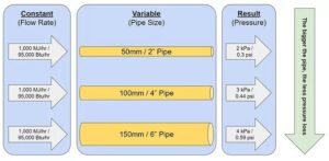
Below, the friction loss chart illustrates how pipe size, flow rate, and pressure drop are connected in any Schedule 40 steel piping system. It plots flow in gallons per minute against friction loss in feet of water per 100 ft (30 m) of pipe.
While gas pipe sizing uses the IFGC equations above rather than this water-based chart, the same underlying friction principles apply. At a glance, the chart illustrates how bigger pipes drop less pressure, and faster flow drops more. In fact, this is the core insight behind every sizing calculation.

Common Gas Pipe Sizing Mistakes
Several mistakes appear regularly in gas pipe sizing work, but most are avoidable with a careful process.
- Ignoring fittings when measuring equivalent length: A run with 10 elbows and 3 tees can add 15 to 20 feet of equivalent length beyond the measured straight-pipe distance. Using only straight-pipe length undersizes the system.
- Using the wrong pressure drop assumption: The standard 0.5-inch water column drop works for most residential systems, but 0.3-inch may be required where inlet pressure is marginal.
- Forgetting to verify appliance input: A 199,000 Btu/h tankless water heater needs far more flow than the 40,000 Btu/h storage tank it replaced. The original pipe sizing may no longer be adequate.
- Omitting diversity factors for large systems: In buildings with many appliances that never run simultaneously, a diversity factor avoids gross oversizing. Missing this step inflates pipe sizes unnecessarily.
- Mixing units in the equation: The IFGC constants (19.17 and 18.93) are only valid with specific unit combinations. Flow must be in CFH, diameter in inches, and pressure in the units each equation requires.
Note: Engineers working in metric units should use the equivalent metric form of the equation with appropriate constants, and confirm the correct form against their applicable local standard.
Example of Gas Pipe Sizing in Practice
To start, consider a small commercial kitchen with a 400,000 Btu/h (117 kW) combination oven, a 150,000 Btu/h (44 kW) griddle, and a 100,000 Btu/h (29 kW) fryer. The total connected load is 650,000 Btu/h (190 kW). Using a natural gas heating value of 1,000 Btu/ft³, this equals roughly 650 CFH. In metric terms, using a calorific value of around 38 MJ/m³, the same load is approximately 18 m³/h.
The longest run from the gas meter to the combination oven is 85 ft (26 m), with an estimated 15 ft (4.5 m) added for fittings and valves. This gives 100 ft (30 m) of total equivalent length. The system operates below 1½ psi (103 mbar), so IFGC Equation 4-1 applies.
Checking the low-pressure table at 100 ft (30 m) equivalent length: a 1¼-inch pipe handles up to 403 CFH — not enough. A 1½-inch pipe (DN40) handles 605 CFH — still short. A 2-inch pipe (DN50) handles 1,165 CFH, which comfortably meets the 650 CFH load with room for future expansion.
Best Practices for Gas Pipe Sizing
Applying this gas pipe sizing guide correctly comes down to a handful of consistent habits.
- Use the connected load, not the appliance nameplate totals: Diversity factors account for realistic peak demand when appliances cycle independently.
- Include equivalent length for all fittings: Use published equivalent length tables, or add a conservative 10 to 20 percent to the measured straight-pipe length.
- Check every branch, not just the longest run: Short branches with high loads can have higher local pressure drop than the longest run.
- Document your pressure drop assumptions: Inspectors need to see the 0.5-inch water column value (or whichever value you used) written directly into the calculation.
- Leave capacity for future expansion: A 10 to 20 percent oversize margin on the main costs little at installation but prevents expensive retrofits when loads grow.
Automate Gas Pipe Sizing With h2x

h2x automates gas pipe sizing, removing manual calculation steps and checking every section against the selected design method and project criteria in real time. You enter the appliance loads, the pipe layout, and the operating pressure, and h2x applies the correct equation. The platform will also flag any runs that fail the pressure drop check.
The software supports far more than Schedule 40 black steel. h2x sizes pipes for copper, stainless steel, cast iron, PEX, and HDPE. Also, it switches to the correct friction characteristics and inside diameters when you change materials. That matters, because using one material’s sizing table for another is a common cause of undersized systems.
Finally, h2x also produces the documentation inspectors and reviewers expect, including a full schedule of pipe sizes, pressure drops, and design assumptions, tied directly to the project drawings.
Watch the demo below to see how h2x handles a full gas pipe sizing workflow in one connected project, or book a 1:1 call to see it applied to your own designs.
Conclusion
Using a gas pipe sizing guide correctly is one of the most consequential steps in any building services design. Getting it right ensures appliances perform as designed, the system meets code, and the building stays safe for its full operating life.
Specifically, selecting the correct sizing equation for your jurisdiction, accounting for equivalent length, and verifying every branch mean the difference between a reliable design and a costly retrofit.
Gas Pipe Sizing Guide FAQs
What is gas pipe sizing?
Gas pipe sizing is the process of calculating the minimum pipe diameter required to deliver the required flow of natural gas or LPG to every appliance at the required pressure.
How do I figure out gas pipe sizing?
The standard sizing process uses the IFGC equations and accounts for total load, equivalent pipe length, and allowable pressure drop. With those values ready, gas pipe sizing can be completed in just five steps, outlined above.
Is there an online gas pipe sizing calculator?
h2x offers a free online gas pipe sizing calculator!
What is the difference between low-pressure and high-pressure gas pipe sizing?
Low-pressure systems operate below 1½ psi (103 mbar) and use IFGC Equation 4-1, which accounts for pressure drop in inches of water column. High-pressure systems
operate at 1½ psi (103 mbar) or above and use IFGC Equation 4-2, which accounts for gas compressibility by working with the difference between the squares of the
upstream and downstream absolute pressures. High-pressure systems carry significantly more flow in the same pipe size but require a line pressure regulator at each appliance to reduce pressure back to operating manifold pressure, typically around 5 inches of water column (1.25 kPa).
What pressure drop should I use for gas pipe sizing?
Most residential and light commercial systems use 0.5 inches of water column (0.125 kPa) as the standard pressure drop assumption. That said, systems with low inlet pressure or long runs may need 0.3 in. w.c. (0.07 kPa) to maintain adequate pressure. High-pressure systems use a psi-based pressure drop, typically 0.5 to 1.0 psi (34–69 mbar) across the system.
What pipe materials can be used for natural gas?
Schedule 40 black steel is commonly used for above-ground gas distribution in many commercial projects, particularly in North America. On the other hand, underground distribution often uses medium-density or high-density polyethylene (MDPE or HDPE). Finally, corrugated stainless steel tubing and copper are both permitted for indoor use in some jurisdictions. Always check the local code before specifying a material.
Which code applies outside the USA?
UK engineers typically follow IGE/UP/2 or BS 6891. European projects reference EN 1775. Australian and New Zealand installations follow AS/NZS 5601. While the underlying hydraulic principles and equations are the same, allowable pressure drops, pipe material approvals, and testing requirements vary by jurisdiction. Always confirm with the applicable local standard.
How do I size a pipe when multiple appliances share a run?
Each section of pipe must be sized for the cumulative downstream load it carries, using the longest equivalent length from the meter to the farthest appliance. This is called the longest-length method, and it is the most common approach specified in the IFGC.
Ready to size gas pipework faster and with confidence?
Check out how engineers calculate pipe sizes, pressure drops, and flow rates across every section of a gas system in one connected workflow, with automatic compliance checks and inspection-ready documentation as a direct output of the design.
Meet the author

Andrew Spencer
Andrew Spencer is a Mechanical Engineer at h2x.
Article Last Updated: May 27, 2026