Sizing Pressure Reduction Valves from Caleffi

SIZING
In order to ensure that domestic water is supplied correctly to the user points, the supply system must be sized to guarantee the design pressure and flow rate at every point.
Correct design is crucial in order to maintain and ensure the right pressure at the supply point.

When the supply pressure is too low, the required flow rate to each appliance is not guaranteed. Conversely, if the pressure is too high, noise and damage to the withdrawal devices and distribution system may occur.
The national technical standards propose various calculation methods for choosing the flow rates. It should be noted that the design flow rate is not the sum of the flow rates of all the installed appliances. Simultaneous demand from all draw-off points is unlikely and is related to the system type and application.
Normative references for designing domestic water systems
Design flow rate calculation
To size the distribution system correctly, the design flow rate must be calculated carefully to avoid the issues associated with oversizing the pipes and various system components, such as pressure reducing valves. In fact, it should not be based on all the draw-off points being active simultaneously, but only a fraction of them.
The following steps are required for correct sizing:
1. Calculate the total flow rate in relation to the number of appliances in the system and their types, referring to the technical standards and manufacturers’ data;
2. Choose the simultaneous factor, or read the diagrams in the technical standards;
3. Define the design flow rate using the diagrams or factors chosen in the previous step.
The simultaneous factor calculation takes the following into account:
- User type and intended use of the building;
- Type and number of draw-off points (appliances);
- Duration of the peak time.
Usually, the more users there are, the lower the percentage of appliances open simultaneously.
Sizing methods nowadays tend to choose lower design flow rates with respect to the
past. The main reasons are:
- Water savings
- User habits
- Hygiene
- New appliances with flow limitations.
Once the flow rate has been defined, the permissible velocity within the pipes must be taken into account in order to size the distribution system. The pressure at the draw-off points must be guaranteed to meet the manufacturers’ instructions or the technical standards.
Selection criteria for PRVs (velocity and pressure drop)
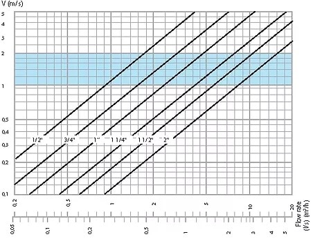
When choosing the most suitable pressure reducing valve, it is advisable to consider a flow velocity range of 1–2 m/s. This range is based on the need to prevent noise and consequently also rapid wear of the components and appliances.
The flow velocity depends on the pass-through flow rate and the pipe cross-section as follows:
Where:
- V = flow velocity (m/s)
- G design = medium flow rate (l/s)
- DN = nominal diameter (mm)
Note that, the size of the pressure reducing valve must be selected to obtain a flow velocity
within the specified range (1–2 m/s). Alternatively, the appropriate diagrams in the technical
product documentation can be used.
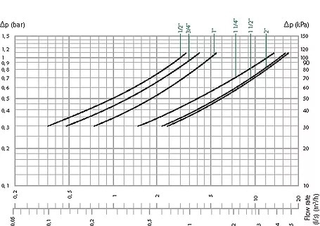
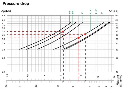
The pressure drop is obtained from the graphs in the technical documentation by intersecting the design flow rate with the curve for the diameter chosen previously. With respect to the set pressure with a flow rate of zero, the downstream pressure, therefore, decreases by a value equal to the pressure drop.
It is important to have a progressive pressure drop, a sudden decrease can cause problems with certain flows.
Pressure Drop
The pressure drop at the design flow rate must always be taken into account when choosing the pressure reducing valve. In addition to verifying the velocity, it is always necessary to check that the pressure drop is not too high, otherwise, a larger size or a different type of pressure reducing valve must be chosen.
Oversizing
Oversizing occurs when the chosen pressure reducing valve is too large in relation to the flow rate through it under nominal operating conditions. An error of this type causes the pressure to be regulated incorrectly.
Design Errors
| Choice of simultaneous factor Error due to choosing simultaneous factors that are incorrect or in any case not in line with the characteristics and intended use of the building. |
| Selection based on pipe size Error due to choosing a pressure reducing valve based only on the system pipe diameter, especially when retrofitting in older, often oversized systems. |
Always make appropriate design flow calculations before choosing the pressure reducing valve and other components to be installed.
By-pass installation
Sizing the pressure reducing valve according to the design flow rate sometimes leads to operating problems when there is low flow rate demand. This condition may arise because of the time of use during the day or due to specific system uses.
Operation outside the working range
| The pressure reducing valve operates with the obturator almost fully closed, and may be unable to regulate the outlet pressure correctly, causing it to fluctuate. The diaphragm becomes unstable resulting in erratic behaviour at low flow rates. This can lead to noise and vibration problems, which are then transmitted to the whole system. |
The solution to this issue is to install two pressure reducing valves in parallel (by-pass) to ensure a stable downstream pressure, even at low flow rates. System operation is fully automatic, based on the actual flow rate.
Installation logic with by-pass pressure reducing valves
- Main pressure reducing valve:
- Sized according to the design flow rate
- By-pass pressure reducing valve:
- Set to approximately 50–70 kPa (0,5–0,7 bar) higher than the setting of the main pressure reducing valve, and sized according to the minimum flow rate demand of the system. The minimum flow rate demand can be assumed to be 20–30 % of the design flow rate.
Operation
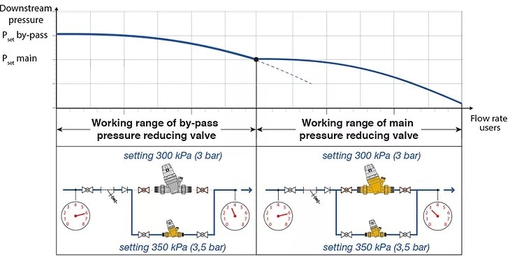
Downstream pressure trend as a function of the flow rate demand
| Low flow rate demand Only the by-pass pressure reducing valve intervenes as it is set to a higher pressure than the main valve. As the flow rate increases, the downstream pressure decreases resulting in an increased pressure drop in the pressure reducing valve. | High flow rate demand The main pressure reducing valve also intervenes, i.e. the one sized for the design flow rate and set to a lower pressure. It starts to open when the downstream pressure reaches the setting value. |
With this system solution, the pressure is fully regulated when the system is operating with a low flow rate. At the same time, the correct pressure is also guaranteed when the design flow rate is used. It is a very useful solution for systems with high flow rate demands during the day or at specific times, and significantly lower flow rates at other times.
Examples of selecting pressure reducing valves
RESIDENTIAL CASE (according to EN 806-3)
Below are some examples of calculations according to the EN 806-3 standard for: •
- Single house, composed of 2 bathrooms and 1 kitchen
- Apartment block composed of:
- 10 apartments (bathroom and kitchen)
- 20 apartments (bathroom and kitchen)
To calculate the total flow rate, the installed appliances are considered, with the flow rates of each appliance.
Where n is the number of appliances of each type.
| Appliance | Unit Flow Rate (l/s) | Single House No. of Appliances | Apartment No. of appliances |
| Sink | 0.2 | 1 | 1 |
| Wash Basin | 0.1 | 2 | 1 |
| Bidet | 0.1 | 2 | 1 |
| WC | 0.1 | 2 | 1 |
| Bathtub | 0.4 | 1 | 1 |
| Shower | 0.2 | 1 | 0 |
| Washing Machine | 0.2 | 1 | 1 |
| Dishwasher | 0.2 | 1 | 1 |
| | Total Flow Rate | 1.8 l/s | 1.3 l/s |
Velocity
| | Single House | 10 Apartment Block | 20 Apartment Block |
| Total Flow Rate | 1.8 l/s | 13 l/s | 26 l/s |
| Design Flow Rate | 0.65 l/s | 1.3 l/s | 1.6 l/s |
| Simultaneous Factor | 36.1 % | 10 % | 6.2% |
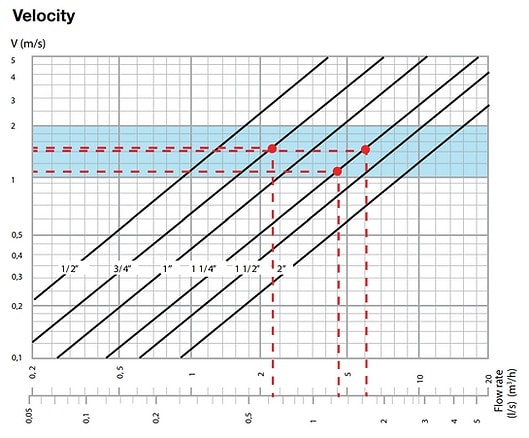
Choice of pressure reducing valve (according to the velocity and pressure drop graphs)
| | Single House | 10 Apartment Block | 20 Apartment Block |
| Nominal Diameter | 20 | 32 | 32 |
| Delta pressure | 70 kPa (0.7 bar) | 55 kPa (0.55 bar) | 60 kPa (0.60 bar) |
COMMERCIAL CASE (according to DIN 1988-300)
Below are some examples of calculations according to the DIN 1988-300 standard for:
- Hotel composed of:
- 10 rooms
- 25 rooms
- 50 rooms
| Appliance | Unit Flow Rate | Hotel Room – No. of Appliances |
| Wash Basin | 0.07 l/s | 1 |
| Bidet | 0.07 l/s | 1 |
| WC | 0.13 l/s | 1 |
| Bathtub | 0.15 l/s | 0 |
| Shower | 0.15 l/s | 1 |
| | Total Flow Rate | 0.57 l/s |
| | 10 Room Hotel | 25 Room Hotel | 50 Room Hotel |
| Total Flow Rate | 5.7 l/s | 14.25 l/s | 28.5 l/s |
| Design Flow Rate | 1.48 l/s | 2.38 l/s | 3.36 l/s |
| Simultaneous Factor | 26 % | 16.7 % | 11.8 % |
Choice of pressure reducing valve (according to the velocity and pressure drop graphs)
| | 10 Room Hotel | 25 Room Hotel | 50 Room Hotel |
| Nominal Diameter | 32 | 40 | 50 |
| Delta pressure | 60 kPa (0.60 bar) | 65 kPa (0.65 bar) | 80 kPa (0.80 bar) |
Choice of by-pass pressure reducing valve
Proceeding with the example of the 50-room hotel, we define how to choose and set the by-pass reducing valve based once again on the velocity. Since this application requires high flow rates at specific times and significantly lower ones at other times, it is necessary to install a by-pass pressure reducing valve.
The main pressure reducing valve is DN 50. The by-pass pressure reducing valve is sized for a lower flow rate than the design flow rate; we assume a flow rate of 25 % in the example.
We always recommend adjusting it on-site during commissioning to ensure all devices operate in the best condition.
50 Room Hotel
| Total Flow Rate | 28.5 l/s |
| Design Flow Rate | 3.36 l/s |
| Simultaneous Factor | 11.8 % |
| Nominal DiameterMain Pressure Reducing valve Set to 300kPa / 3 bar | 50mm (2″) |
| Delta pressure | 80 kPa (0.80 bar) |
BY-PASS PRESSURE REDUCING VALVE – Set to 370 kPa (3,7 bar)
| Minimum flow rate demand is 25 % of the design flow rate | 0.84 l/s |
| By-pass pressure reducing valve Nominal Diameter | 25mm (1″) |
| Delta pressure | 65 kPa (0.65 bar) |
PRESSURE CONTROL
Pressure reducing valves serve to maintain the pressure and ensure that it is correct at the draw-off point, usually in the range of 150 to 300 kPa (1.5 to 3 bar). Always refer to the technical data sheets provided by the appliance manufacturers to verify if they have different working ranges.
| LOW PRESSURE | OPTIMAL PRESSURE | EXCESSIVE PRESSURE |
| 0 kPa < P < 150 kPa (0 bar < P < 1.5 bar) | 150 kPa ≤ P ≤ 300 kPa (1.5 bar ≤ P ≤ 3 bar) | P > 300 kPa(P > 3 bar) |
  |   |   |
Two main conditions can occur in domestic water systems:
1. The mains pressure is too high and therefore must be reduced at the inlet;
2. The mains pressure is too low and must be increased with pressure boosting units.
In high-rise buildings, the thrust needed to ensure the required pressure at the higher floors may be too high for the lower floors, so the best compromise has to be found between the pressure boosting unit setting and the locations of the pressure reducing valves.
In buildings with several floors, the hydrostatic height results in an equivalent decrease in the pressure available at the taps. The hydrostatic pressure trend is shown below, considering each floor to be 3 metres high, therefore with a ΔP of 30 kPa (0,3 bar) from one floor to the next
When choosing the correct location for the pressure reducing valves, it is also important to consider the pressure drops due to dynamic effects. In particular, we must prevent the most favourable areas from subtracting pressure from the farthest areas. When the pipes are undersized and long, the pressure drops due to dynamic effects become considerable, especially in the farthest units. The pressures are lower at these points and may be insufficient for the user.
When choosing the pressure reducing valve, it is necessary to consider that it can vibrate and cause noise in certain operating conditions. In some systems, to avoid problems related to cavitation and noise, specific solutions have to be adopted to ensure that the pressure reducing valves can operate correctly within their working range.
Cavitation and noise
A key consideration when choosing and locating pressure reducing valves is cavitation, the cause of many noise and vibration issues. It is typical of hydraulic systems and consists of the formation of small vapour bubbles, which can damage pipes and components as a result of rapid collapse.
Noise in pressure reducing valves may be a clear indication that they are operating in improper working conditions. If the pressure reduction ratio, i.e. the ratio between upstream pressure and downstream pressure, is too high, the water becomes very fast in the restricted cross-section. This generates a local pressure drop (according to Bernoulli’s equation) until the vapour pressure of the liquid is reached.
This condition causes the liquid to change to the gaseous phase, forming bubbles that contain vapour.
When the bubbles implode, it causes pressure fluctuations charged with impact energy. Together with the high water velocity in the gap between the seat and obturator, this can compromise the components in the pressure reducing valve, creating mechanical vibrations, noise and material erosion. The phenomenon is increased if the water contains dissolved air.
Vapour pressure varies with water temperature. There is a much greater risk of cavitation in hot water as the vapour pressure is higher. For example, the vapour pressure (Pv) at 60 °C is about 20 times greater than at 10 °C.
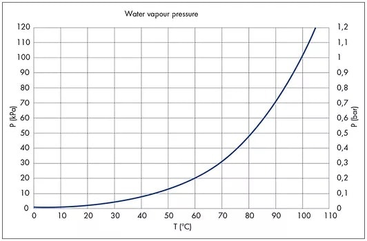
Cavitation diagram
To minimise the risk of cavitation in the pressure reducing valve, we strongly recommend referring to the working conditions specified in the cavitation diagram.
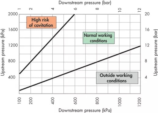
| HIGH RISK OF CAVITATION: The reduction ratio between upstream and downstream is too high and therefore the onset of cavitation is very likely. |
| NORMAL WORKING CONDITIONS: The pressure reducing valve works with the correct reduction ratio, and therefore without cavitation. |
| OUTSIDE THE WORKING CONDITIONS: The pressure reducing valve cannot operate as the upstream pressure is lower than the downstream pressure. |
Numerous factors and variable conditions can affect the behaviour of pressure reducing valves, including system pressure, temperature, presence of air, flow rate and velocity. We recommend keeping the ratio between the upstream and downstream pressures ideally at 2:1 and no higher than 3:1 (maximum recommended pressure reduction ratio). In such conditions, the risk of cavitation is reduced to a minimum, nevertheless, this does not completely exclude potential effects due to the other numerous factors present inside the system during operation.
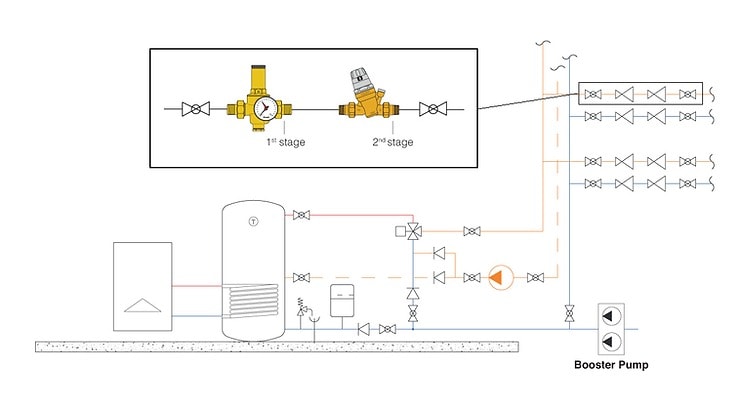
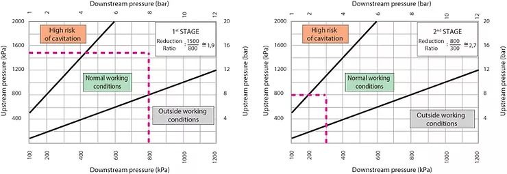
Pressure reducing valves in series (double stage reduction)
In system applications for which a high pressure must be guaranteed in order to supply the users at the top floors, some measures must be taken to ensure that the pressure reducing valves at the bottom floors do not work in conditions at risk of cavitation.
This situation can also occur when the mains pressure is already very high. One of the solutions that can be adopted is to install several pressure-reducing valves in series so that they share the pressure drop.
Assuming an inlet pressure of 1500 kPa (15 bar) and a desired pressure of 300 kPa (3 bar) at the users, the reduction ratio is too high (5:1). Therefore the following must be installed:
- a first stage pressure reducing valve to perform an initial pressure reduction: generally it can be a device with less accurate regulation, but with high mechanical resistance since it is subject to the mains pressure peaks and variations
- a second stage pressure reducing valve installed in series with the first to reach the desired pressure: generally it must be able to guarantee accurate regulation to the users, and is also less subject to pressure peaks and fluctuations since its operation is protected by the first stage.
Reduction Ratio
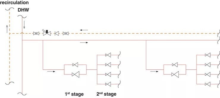
Combined by-pass/series application
In some installations, it is also possible to opt for more complex system solutions, consisting of pressure reducing valves in parallel and pressure reducing valves in series. This ensures that the pressure is controlled optimally in both design flow rate conditions and low flow rate conditions. Series installation also allows low reduction ratios. For the sake of simplicity, the diagram shows only the domestic hot water circuit, but the same considerations can also be applied to the cold water circuit.
Big thanks to Caleffi for sharing this informative blog post with us. All text and images are copyrighted to Caleffi. For more information visit www.caleffi.com
H2X partners with All Valve in Australia, a leading distributor of Caleffi products. If you need any information please contact Daniel Dillenbeck at daniel@allvalve.com.au
Want to know more about Pressure Reducing Valves? Check out another one of our blog posts at the link below.
7 Important Steps for Designing Pressure Reduction Valves
Did you know?
You can design using Caleffi’s PRV’s in H2X.
Simply add PRVs to your system, input the required outlet pressure and H2X will calculate the size based using the flow rate, inlet pressure and Caleffi’s guidelines, as well as advising if a bypass or series setup is required. Try it yourself for free!

5 Reasons Industry Experts Design with H2X
- Exceptional Support
- Proven & Reliable
- Ease Of Use
- Built By The Industry
- Worldwide User Base
What's in the Pipeline?
Get access to our monthly roundup of news and insights
You may unsubscribe from these communications at any time. For more information, please review our Privacy Policy.