Gas Pipe Sizing in 4 Simple Steps
When undertaking gas pipe sizing, the pressure loss through the pipes cannot exceed the difference between the starting pressure and the pressure required at the appliances.

Download your free PDF of this article below.
When undertaking gas pipe sizing, the pressure loss through the pipes cannot exceed the difference between the starting pressure and the pressure required at the appliances.
Based on the example image above, if you need 2.75 kPa / 0.4 psi at the appliance:
- The 50mm / 2" pipe is too small
- The 100mm / 4" pipe is sufficient
- The 150mm / 6" pipe is sufficient but unnecessarily large (not cost-effective)
Now let's work through a simple example project together.

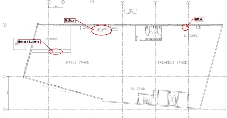
Step 1 – Where are the gas requirements?
To inform the gas pipe sizing, find out from the project team which appliances require gas.
In this example, we have stoves in a kitchen, bunsen burners in a classroom, and boilers in the plant room.
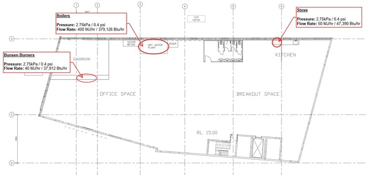
Step 2 – What are the requirements?
You can find out the requirements by asking the relevant project team member or looking up the technical data of the appliance. The information you need to know is the flow rate of the appliance and the inlet pressure.
In this example, all appliances have differing flow rates with the same inlet pressure of 2.75 kPa / 0.4 psi.
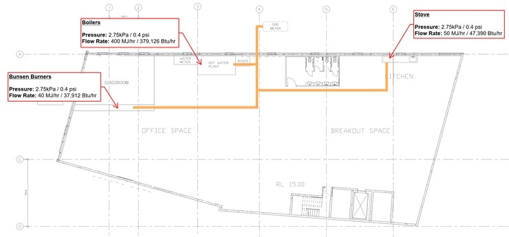
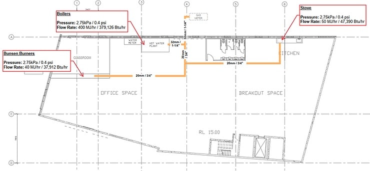
Step 3 - Draw the pipe layout
In the most efficient way possible, draw the pipe layout from the gas meter to the appliances (minimise the amount of pipe and fittings).
Step 4 – Gas Pipe Sizing
First, you need to determine the index length. The index length is the route from the gas meter to the furthest appliance.
As you can see in the example below, the stove in the kitchen is the furthest away appliance and is therefore the index length (highlighted in yellow).
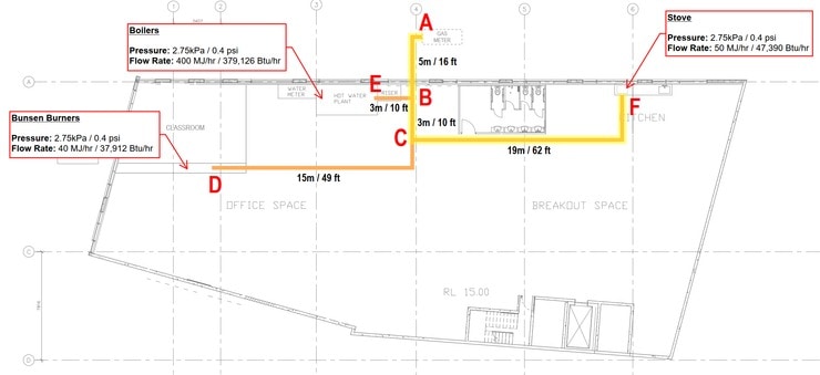
The index length from A-F is 27m / 88 ft. It is common practice to add 20% to the index length to cater for pressure loss through bends and fittings. This makes the index length 33m / 108 ft.
From here we can create a table to record the pipe sizes for each segment. The process to follow for each pipe segment is:
- Always use the index length; and
- Use the combined flow rate of the downstream appliances.
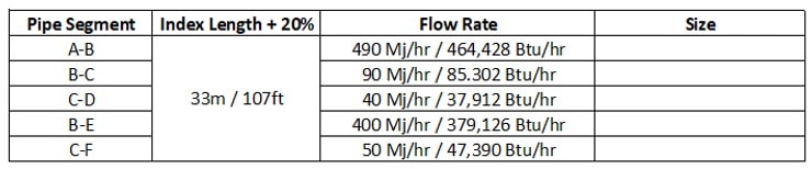
Now we can use a spreadsheet or pre-calculated tables to fill in the 'size' column on the table.
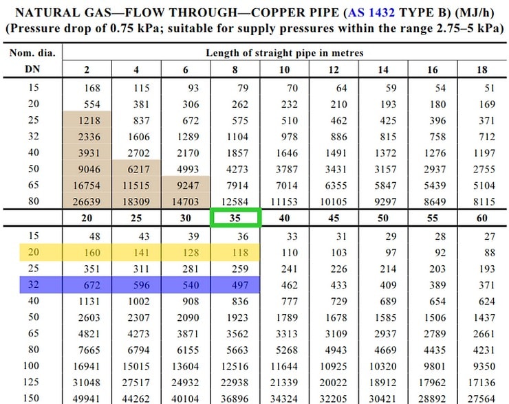
Using the pre-calculated table below, the index length is rounded up and shown in green. The pipe segments B-C, C-D, and C-F are shown in yellow, B-E and A-B is shown in blue.

How do I read the below table?
- Find the length of the pipe that is equal to or greater than the index length; then
- Make your way through the below numbers until you find the first one that is equal to or greater than the flow rate; then
- Look horizontally to the left to find what the corresponding pipe size is.
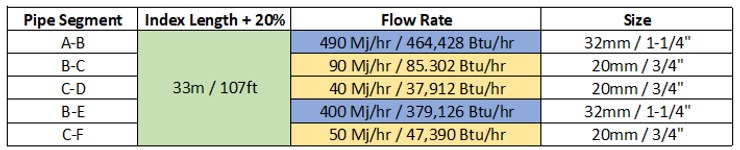
Now we can complete the gas pipe sizing table with the results.
Then the last step is to show the gas pipe sizing on the drawing.
Additional Information on Gas Pipe Sizing
Other items that you will need to consider on more complex projects are:
- Diversity – if you have lots of appliances, they will not operate simultaneously so you do not need to allow for 100% demand in the gas pipe sizing
- Minimum pressure - you may have appliances that have different maximum pressure requirements, in this case, it would be best to use the most onerous
- Height – if you have a very tall building, the height will affect your calculations
A better way to do gas pipe sizing
The video below shows a better way to size a gas system using H2X’s design and calculation software. Not only does it automatically provide the results as you draw out the system, but it is also flexible to suit future design changes, you automatically get the cost of the system, it is easy to review, and you get a clear digital markup that you can share with the project team.
You can start a free trial of H2X today.
5 Reasons Industry Experts Design with H2X
- Exceptional Support
- Proven & Reliable
- Ease Of Use
- Built By The Industry
- Worldwide User Base

What's in the Pipeline?
Get technical resources delivered to your inbox weekly!